Bearings that slide and roll
Special cylindrical roller bearings allow two simultaneous motions of a shaft – rotation and axial oscillation.
Bearings for shafts that oscillate axially as well as rotate offer a special challenge to rolling bearing designers. Such shafts exist in many branches of industry and include inking and damping rolls in printing machines, jigging rolls in textile machinery, and rolls in belt grinders and leather treatment equipment, to name just a few.
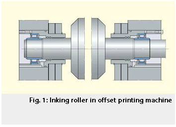
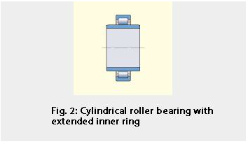
Here the focus will be on bearings to support the inking rolls of printing machines, touching on their design, selection, calculation, arrangement and lubrication. Traditionally inking rolls, used to spread ink on the rotary printing cylinders, have been supported in plain bearings. However, these plain bearings are being increasingly replaced by rolling bearings. Experience has shown that cylindrical roller bearings with an extra wide inner ring are the best solution for this particular application because the linear movement can be accommodated within the bearing itself.
Other types of rolling bearing used for this combined rotational/linear movement include:
- needle roller bearings with extended inner ring,
- deep groove ball bearing/linear ball bearing combinations,
- alignment needle roller bearings with extended inner ring,
- combinations of needle roller and spherical plain bearings,
- multi-row ball bearings for doctor rolls and
- single row ball bearings with special cage guidance.
The linear oscillation of shafts is normally actuated by one of four types of drive: grooved cams, worm gears, or mechanical or pneumatic control units. Cam and worm gear drives have a constant speed/oscillation ratio whereas oscillation is independent of the speed for the mechanical and pneumatic control drives.
Inking roll bearings
The inking roll cylindrical roller bearings are based on single row bearings of the NU design but have a much wider inner ring to allow rather large linear movements. The rollers and cage assembly is guided between integral flanges on the outer ring. The actual bearings have been tailored to individual applications and comprise
- a standard outer ring.
- a standard roller set in a standard cage.
- a special inner ring.
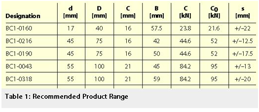
The Recommended Product Range is shown in Table 1. Other sizes can be made available. The bearings have C3 radial internal clearance as standard. This is greater than normal to prevent them becoming blocked, as the inner rings heat up more in operation than the outer rings.
In Table 1, s represents the distance by which the outer ring can be displaced axially with respect to the inner ring from the central position and is referred to as the stroke for these bearings.
Operating conditions
The application considered is that when the shaft on which the bearings are mounted is an integral part of the inking roll. There is another type of inking roll where the shaft and roll are supported separately – the so-called four-bearing arrangement – but this will not be dealt with here.
The cylindrical rollers of the bearings roll in the circumferential direction and simultaneously slide on the inner ring in a direction at right angles to that of rolling. This relative sliding S is defined by the ratio of the sliding distance a to the rolling distance r.
 (1)
(1)
If the axial displacement on the inner ring is constant, the relative sliding for constant sliding velocity is determined using
 (2)
(2)
and similarly for axial displacement in the outer ring
 (3)
(3)
where
| a | = amplitude of the axial oscillation corresponding to half the stroke [mm] |
| dm | = mean diameter of bearing = 0.5(d + D) [mm] |
| Dw | = diameter of cylindrical roller [mm] |
| F | = diameter of inner ring raceway [mm] |
| E | = diameter of outer ring raceway [mm] |
| na | = frequency of axial oscillation [min-¹] |
| ne | = rotational speed of outer ring [min-¹] |
| ni | = rotational speed of inner ring [min-¹] |
When the axial velocity varies sinusoidally (e.g., when crank-driven) the relative sliding varies between a maximum value and zero. This maximum value is 1.575 times the value for constant sliding velocity.
Fig. 3 is a graphic representation of equations 2 and 3 and is valid for a mean relative sliding corresponding to a constant axial velocity of oscillation.
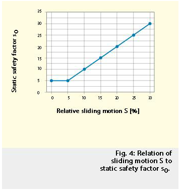
To select the correct size of bearing, it has been found by experience that the relationship of the relative sliding and the static safety factor s0 can be used. This has been confirmed by dedicated tests. The static safety factor s0 is defined as the basic static load rating of the bearing C0 divided by the equivalent static bearing load P0, i.e.
 (4)
(4)
where
P0 = the radial load Fr acting on the bearing for cylindrical roller bearings. To obtain correct bearing performance the intersection of the relative sliding S and the static safety factor s0 should lie above the curve shown in Fig. 4 and the value of s0 should always be greater than 5. If these two criteria are not fulfilled there is a risk that the bearing may fail prematurely.
It is also necessary to calculate the life of the bearing using the classic life equation (to ISO 281:1990)
 (5)
(5)
where
| L10 | = basic rating life [million revolutions] |
| C | = basic dynamic load rating [N] |
| P | = equivalent dynamic bearing load [N] |
| p | = exponent = 10/3 for roller bearings |
As cylindrical roller bearings can only carry radial load P = Fr = the radial load acting on the bearing.
Lubrication
Lubrication is critical for the operational reliability of the bearing arrangement and determines whether the bearing will achieve its theoretical life or not. Practical experience has shown that grease is a suitable lubricant for cylindrical roller bearings with extended inner ring. The trend in the printing industry is also towards grease lubrication and maintenance-free units.
It is, however, important to choose a suitable grease and also to use an appropriate quantity of the chosen grease. Because of the sliding movements experienced in the bearings in the inking roll applications, an EP grease is preferred and the SKF grease LGEP 2 has proved to be very good.
- This grease is based on a
- mineral oil with a kinematic viscosity at 40 °C of 200 mm²/s,
- has a lithium soap thickener,
- can be used at temperatures between –20 and +110 °C, and
- has a consistency of 2 to the NLGI scale. The SKF grease LGEP 2 is
- very suitable for strong vibrations and shock loading conditions,
- suitable for heavy loads,
- has good rust inhibiting properties, and
- is resistant to water.
The appropriate quantity to be applied to the bearing for the first lubrication is determined from
 (6)
(6)
where
| Qinit | = grease quantity for initial fill [cm³] |
| D | = bearing outside diameter [mm] |
| C | = bearing outer ring width [mm] |
The quantity of grease to be applied when relubricating depends on the relubrication interval chosen by the machine operator. Guideline values can be obtained using
 (7)
(7)
where
| Qrel | = grease quantity for relubrication [cm³] |
| D | = bearing outside diameter [mm] |
| B | = bearing inner ring width [mm] |
| ti | = relubrication interval chosen by the operator [h] |
| tf | = relubrication interval obtained from SKF General Catalogue 4000 [h] |
The normal relubrication interval chosen by machine operators is between 1,000 and 2,000 h. The maximum relubrication interval obtained from the General Catalogue (scale b) is 25,000 h.
Care must be taken not to fill the bearing with an excessive amount of grease, as this will increase the friction and cause bearing temperature to rise. Furthermore, it is recommended that the bearing be run in after having been filled with grease.
Conclusion
Because of the prevailing load conditions and the combination of bearing rotation and recurrent axial displacement, the demands placed on bearings for the type of operation performed by inking rolls are extremely high.
SKF has found the solution in cylindrical roller bearings with extended inner ring. These bearings meet the demands in every respect, accommodating the reciprocating axial motion within the bearing itself. The diagrams and equations presented here have been well proven in service and can be used to select the appropriate cylindrical roller bearing.
Andreas Kraus
SKF GmbH, Schweinfurt, Germany


