Linear guidance systems
In the linear guidance or table systems market, a significant number of users are now seeking to obtain the complete system – guide system, drive and conversion parts – from a single supplier.Table systems are common in measurement applications, the optical industry and in the electronics industry where mechanical systems are required for special purposes.
These systems are usually manufactured in specified construction sizes. In contrast, for the general mechanical engineering sector each table is designed for a specific application. This means that integrated table units are often manufactured in low numbers at high cost.
For linear guidance systems about 80% of requirements can be satisfied with a limited number of construction units. If users are prepared to accept standard sizes, such systems could be produced more economically yet fulfilling all required specifications and incorporating the latest techniques in guidance and drive technology.
Precision is leading factor
A survey of the German mechanical engineering sector has shown that the most important requirements of the market are precision, rigidity, travel speed and operational reliability. This market is characterised by technically advanced products and future products have to meet ever higher standards.
Economic considerations tend to take second place both for the manufacture and operation of table systems. Of more concern is the cost of installation and maintenance.
Any manufacturer of standard sizes of table systems has to be aware of the overall equipment designer’s need for flexibility. The supplier has to be able to provide a sensible and rational range of module sizes.
Linear guides top choice
About 60% of all users in the general mechanical engineering sector choose linear guides on the basis of the rolling bearings used. They must meet high demands as well as operate economically. Of this group, 40% were prepared to buy pre-fabricated table systems and have them integrated into their machines. The remainder wished to continue buying individual components from sub-contractors. These respondents gave a number of reasons for continuing this approach including a free choice in construction sizes, better utilisation of in-house manufacturing capacity, integration of bearing in the machine bed and having the advantage of in-house design expertise.
A research project sponsored by the German Ministry of Research and Development for a lathe for ultra-precision machining showed that there remains considerable market potential for guide systems incorporating rolling bearings. Substantially improved performance can be achieved with the right choice of guide design and careful installation.
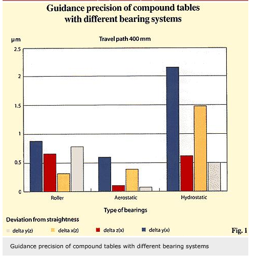
Three tables of similar design were manufactured for this project, guided aerostatically, hydrostatically and by rolling bearings. Measurements of straightness deviations show clearly that guides with rolling bearings can achieve levels of performance comparable to aerostatic guides (fig.1).
Linear drives
For linear drives, most applications favour the ball screw drive. If higher demands are placed on stiffness and positioning accuracy, then the roller screw drive is preferred even though this is more expensive. These drive systems are fitted either with a stepped motor or, for high drive forces, with a servomotor. Incremental measurement sensors, which are normally fitted to the drive motor, are used to determine the position. Measurement systems of this type suffer from the disadvantage that play and elastic deformation in the drive train lead to increasing failure to meet stated tolerances. In high value equipment, control requirements often result in linear measurement systems being installed in the guide system to monitor the precise position of the upper table. Such systems can reach positioning accuracies of ±1 µm. If travel speed of more than 60 m/min is required then either rack and pinion or toothed-belt drives are used. Such systems, however, are not well-suited for highly accurate positioning either because of their elastic properties or because they are specially tailored and can only perform well under limited circumstances.
A market has recently emerged for linear motors to act as a direct drive source for such high speed applications coupled with accurate positioning. Linear motor technology has been available for some time but it has only recently been fully exploited, thanks to the development of highly dynamic control and measuring systems.
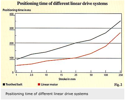
Figure 2 shows a comparison of the positioning times between linear axes of the same design. One is powered by a toothed-belt drive, the other by a linear motor. The travel speed and positioning precision of the linear motor are independent of stroke length and its acceleration behaviour accuracy is such that there is no overshooting. It shortens overall positioning time by up to 50% in comparison with the toothed-belt drive. Levels of position accuracy of ±10 µm have been achieved over the entire travel path.
New focus on table systems
On the basis of market analyses and recent developments, SKF Linear Motion has set the objective of establishing an additional focus for the development, manufacture and marketing of table systems. A considerable market potential exists taking into account the fact that about 17% of the manufacturing costs of a machine tool is related to the manufacture of powered tables. In this sector of German manufacturing the trend is to move away from vertical manufacturing. New partners are being sought since system suppliers can provide subsystems ready for immediate installation.
The aim of SKF Linear Motion is to offer manufacturers sub-systems that meet and exceed performance requirements. Economic manufacture can be achieved by limiting variants but still meeting specifications.
The accuracy of movement was previously dependent on two factors and could only be determined after manufacture. The first is the precision of individual components. The second is care in assembly. Today, optimum matching of the guide elements gives the required accuracy. The preload is also matched to the operating conditions. Performance characteristics such as deviation from straightness and overall positioning accuracy are measured and recorded.
This will simplify the designer’s work by eliminating a significant element of design. Now all that is required is to specify the mechanical interface and decide on the type of layout for the main axis and the attachment arrangement for the slide unit. The machine designer can list required parameters and an overall solution can be created with the involvement of SKF computer programs and experts.
The reduction of sub-assembly suppliers has a number of benefits, including improved delivery times and a product in which final test and qualification has been carried out prior to delivery. Complete sub-assemblies also simplify and reduce repair costs because standard components can be supplied. These benefits also apply to maintenance.
Machine performance can be maintained and enhanced.
The modular concept allows individual tables with the same external dimensions and mechanical properties to be equipped with different drive concepts. Depending on the requirements for dynamics or precision, a combination of conventional drives and direct drives such as linear motors can be easily accommodated.
Integrated linear motors
Linear motors offer particular properties to the machine designer. They require less space, permit the available length of the table system to be optimally utilised and allow a more compact design overall (fig. 3).
Conventional induction motors consist of an inner moving element, the rotor, surrounded by an outer stationary element of field coils. In a linear motor, this arrangement is unpeeled so that the field coils are laid flat and the motor moves in a straight line.
Linear motors consist of a winding section through which current flows, the primary section, which is normally built into the moving upper section of the linear motor table, and the secondary section. Depending on the design this secondary section is either a permanent magnet or a toothed rail and is integrated in the stationary lower section of the table. A selection of linear motor components is shown in figure 4.
A linear measurement system is used for the precise position determination of the upper section of the table and partly for the commutation of the motor. It is installed parallel to the travel axis in the table system. As a rule, incremental linear measuring systems used have a resolution of between 5 and 0.005 µm depending on the application. The linear guide system incorporated in the table system is matched in terms of its properties to user requirements and the linear motor. It takes care of the transfer of the external load, provides the guidance accuracy of the table system which is required transverse to the direction of travel and also maintains the air gap between the primary and secondary section at a constant distance.
Some linear motor systems have relatively high forces of attraction between primary and secondary sections. These have a direct relationship to the drive forces of the motor system and in this context, guide systems with rolling bearings have proved useful. Precision rail guidance systems can work even in the sub-micrometre range. They possess high stiffness and, because of the attraction forces of the linear motor, they operate under optimum preload conditions. This means that even under rapid acceleration no slip movements occur between the rolling elements and the raceways.
Linear motors also allow several table top sections to be operated on one common base but independently of each other. This is achieved by use of a uniform secondary section coupled with the measurement strip for the measurement system. Each top section has its own reader head.
High-precision synchronous movement of two parallel axes, which is required with a gantry structure, can be achieved with the appropriate control design. Measurements on a gantry structure which was operated with two linear motor axes with a travel path of 1,200 mm and a system resolution of 2.5 µm showed a degree of positioning uncertainty during testing of ± 8µm from the reference target position.
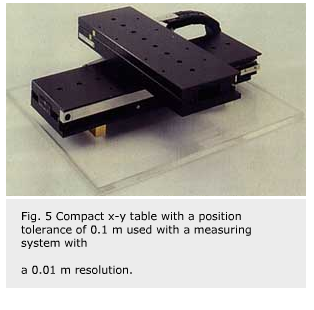
Ultra-precision machining work presents another range of applications. State-of-the-art design for x-y tables have positioning accuracy in the nanometre range. Figure 5 shows a compound table which has a positioning tolerance of 0.1 µm when used with a measuring system with a resolution of 0.01 µm.
Designing with linear motors
Prevailing operating conditions must be known when incorporating linear motors in a table system. The drive force applied by the linear motor must be sufficient to accelerate the total mass to be moved within an acceptable time and to counteract external forces. It must also have sufficient force in reserve to be able to balance out deviations from controlled variables, should this be required.
With conventional drives overloads can be accommodated by the self-inhibition characteristics of a spindle drive. With a linear motor such a facility does not exist. With a correspondingly high deviation from the controlled variable, the linear motor switches off to prevent destruction from overheating.
This highlights one of the weaknesses of the linear motor. In the event of power failure or controller disconnection, the motor stops functioning. Consequently it has no residual retaining force. This has to be compensated for by an additional mechanically actuated and electrically ventilated braking device. Such devices are particularly important for vertical drive systems.
For directly driven table systems the correct choice of measurement system, resolution and mechanical coupling to moving parts is important. The linear motor control may allow for positioning in the range of the measurement system. It is better, however, to select a resolution that is at least five times higher than the degree of positioning required. In this case the fact that the resolution can have an effect on the maximum speed of the drive needs to be borne in mind.
Hermann Glöckner,
SKF Linearsysteme GmbH,
Schweinfurt, Germany


