New SKF engineering software for the evaluation of bearing arrangements
SKF SimPro Quick is an easy-to-use bearing analysis tool with advanced features.
SKF SimPro Quick single-shaft bearing-simulation software was developed to quickly evaluate the design of bearing arrangements and their field performance based on relevant application requirements and conditions. The goal was to provide designers with more SKF engineering knowledge and autonomy in order to accelerate their design process and optimize the selection of appropriate bearings.
Accurate data in a user-friendly interface
One of the key values of SKF SimPro Quick lies in SKF’s core expertise in and knowledge of the application of bearings in rotating machines. This is embedded in powerful simulation software that has a simple and easy user interface, thus providing customers with the best user experience possible. The software has been developed on the same platform as the most-often-used application engineering software in SKF, SimPro Expert, which also makes it simple for any user to take the discussion with SKF on bearing arrangements even further.
Bearing selection
Another great strength of the software is that it enables customers to select bearings directly from SKF’s new Rolling Bearings Catalogue 17000, ensuring that the latest updates are taken into account. As in SKF’s product catalogues, one will immediately be able to see whether the bearing has SKF Explorer performance quality or is a popular item. The latter functionality enables the customer to devise a bearing arrangement based on commonly used high-volume items.
The access to SKF’s vast bearing database gives the customer numerous options for designing an optimal bearing arrangement – everything from two bearings on a shaft to as many bearings as required.
Application modelling and bearing performance analysis
Building a complete model requires only a few steps. As an example, a jackshaft for a screw compressor is shown. Operating screw compressors at various power levels changes the output of the machine. Varied speed and torque impact the forces occurring at the gear mesh. This in turn affects bearing performance. In the following we explain step by step how SKF SimPro Quick can help designers optimize the design of a bearing arrangement and reduce testing time for a range of various operating conditions.
STEP 1 – Components
![]()
- shaft
- bearing selection
- gears
- springs
- spacers
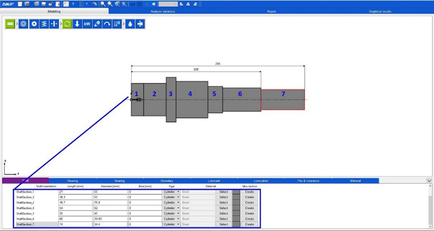
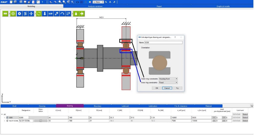
The first step (fig. 1) is building the application model using the most common components, such as bearings, gears, springs and spacers. All of these components are incorporated in the model by a drag-and-drop process onto the shaft. Once the shaft is defined, bearings may be easily added to the shaft with the drag-and-drop feature. A walkthrough process can be used to select the bearings based on the shaft diameter at the bearing seat, bearing type (deep groove ball, angular contact ball, cylindrical roller, etc.) and any partial bearing designation, if known. The next action of the walkthrough process defines how the bearing is mounted on the shaft and in the housing (fig. 2).
Dragging a gear onto the shaft initiates a guided walkthrough similar to the process with the bearings. For gears, the type is defined (bevel, helical, hypoid, spur or worm); then the user is asked to enter gear geometry. Finally, the user inputs the power to the gear, a factor that is used with the geometry to automatically reconcile different gear forces. The steps to add a gear greatly support design and analysis of gearbox shaft applications.
Springs bring the ability to preload bearings against a ground (such as the housing) and preload against another bearing. This ability is useful for applications where springs are used to locate a bearing or meet minimum load requirements for applications such as pumps, compressors and electric motors.
Spacers provide the ability to set defined endplay values, which is useful for applications having back-to-back or face-to-face bearing arrangements.
STEP 2 – Boundaries
![]()
- rotational speed
- external forces (loads)
- power (gear)
- moments
- gravity
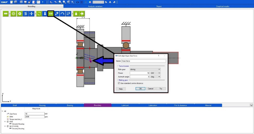
The second step consists of applicable boundary conditions. Shaft rotational speed, radial and axial forces, power input (gear) (fig. 3), moment load and gravity can be added to the model. Similar to the components, force, power input and moment are applied by drag and drop; the other boundaries are simply an icon click. All of the applicable boundaries can be varied in the “Analysis variations” portion of the program with the exception of gravity. The method for applying gravity enables the user to study applications not only in the horizontal position but also in the vertical position.
STEP 3 – Lubrication and bearing clearance
![]()
- lubrication
- fits and clearance
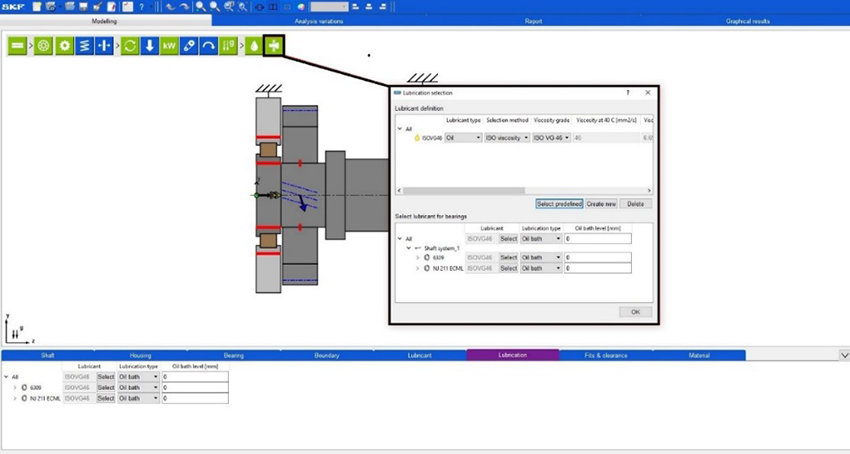
Included in the third step are the lubrication and fit conditions. SKF SimPro Quick provides the ability to define the lubrication method (grease, oil bath or oil spot), oil viscosity and contamination levels (fig. 4). All these lubrication properties impact outputs ranging from the relubrication interval to bearing friction.
Bearing fits are the final selectable item. Fits are a crucial point in the designing process. Selection of the correct fits is critical in providing good operating conditions. A click on the icon opens a sub-window, enabling the user to modify shaft and housing fits, initial internal bearing clearance and inner and outer ring temperature values, all of which impact the operating bearing clearance. The review of clearance reduction is important in applications with heavy press fits or for applications where inner ring temperatures are significantly higher than outer ring temperatures. These are typical application conditions where the initial internal clearance may be insufficient to overcome the clearance reduction in operation and may result in preload. The user may select a different clearance class to obtain appropriate bearing (operating) clearance.
Analysis
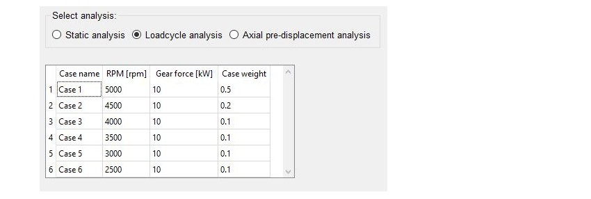
After the user works through the initial steps and completes the model, an option is provided to run a single data set analysis (single analysis) or to run several conditions (load cycle analysis) based on the defined operating boundaries (fig. 5). Multiple conditions are defined using a table interface. An option is available to provide a time weight portion for each step, which is useful when determining bearing life over several different operating conditions.
Results and output
Output of the analysis includes several data tables and visuals that enable the user to create a preferred template set-up for the report. Typ-ical tables show, e.g., bearing loads, operating internal clearances, friction, misalignment, deflection and SKF rating life as well as a modified rating life according ISO/TS 16281:2008.
Basic rating life (L10), modified reference rating life (L10mr) according to ISO/TS 16281:2008 and SKF rating life are the most-often-used tables when reviewing applications and bearing selection. This is typically due to the industry placing heavy focus on L10 fatigue life to determine how long bearings can operate. With the results of SKF rating life, full SKF Explorer effect is achieved. But the results from SKF SimPro Quick go a step further. They also define conditions where bearings may experience lower service life compared with calculated L10 fatigue life. Excessive misalignment, insufficient loading, overloading and an excessive running speed are warnings that are provided if operating conditions are violating any of the recommended conditions (fig. 6). This raises user awareness of conditions that may impair service life and prevent the bearing from reaching the traditionally used L10 fatigue life.
Other tables in the output provide important details about relubrication intervals, operating clearance, bearing defect frequencies and gear forces.
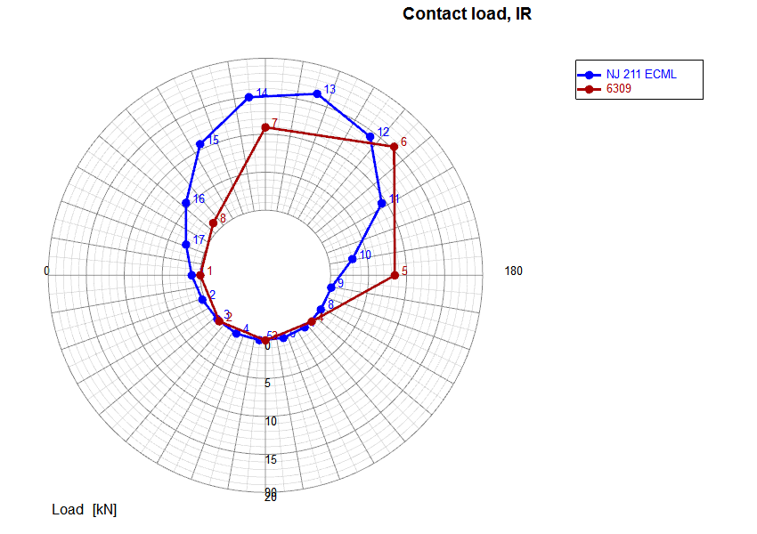
Visual plots and animations add to the level of result details. Polar plots for contact angle, contact deformation and contact load are provided to indicate conditions for each rolling element of the bearing (fig. 7). Comparing multiple data polar plots together may, for example, point to an unsatisfactory operating condition such as heavy load concentration or high contact angle.
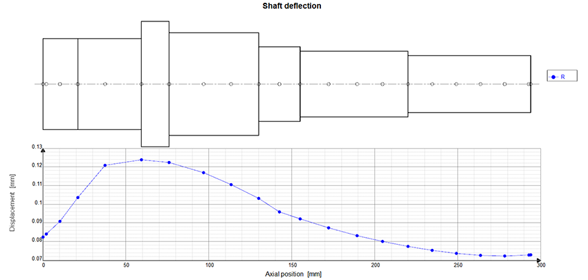
A shaft deflection plot demonstrates deflection along the shaft given applied operating conditions. Possible seal contact clearance, shaft movement relative to other components (example: impeller location relative to housing) and shaft bending stress may be derived from the deflection curve (fig. 8).
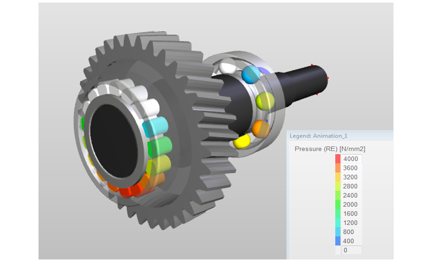
Three-dimensional animation is included to examine roller pressure distribution in the bearing and boundary conditions’ impact on shaft and bearing movement (fig. 9). This visual tool has been used by SKF engineers to better visualize bearing loading and component deflection of the shaft as well as the bearing rings and rolling elements relative one to the other.
SKF SimPro Quick is part of the SKF engineering tools portfolio
SKF SimPro Quick is one of a comprehensive list of engineering tools developed by SKF to support engineers and customers in selecting an optimal bearing arrangement. Each tool has a set of functionalities and features based on the required evaluation accuracy, the complexity of the application and its operating conditions. For SKF’s general bearing product assortment, the following tools are available, ranging from easy and fast to very advanced and comprehensive:
- SKF Bearing Calculator: online, easy-to-use single-bearing selection and calculation
- SKF Bearing Select: online, easy-to-use bearing set selection and calculation
- SKF SimPro Quick: quick and advanced single-shaft simulations
- SKF SimPro Spindle: quick and advanced spindle-application simulations
- SKF SimPro Expert: advanced and comprehensive multiple-shaft application simulations.
SKF SimPro Expert and SKF SimPro Quick are trademarks of the SKF Group.
SKF Explorer is a registered trademark of the SKF Group.


