Reduced noise and vibration with computer simulation
A new computer program that simulates vibrations in rolling bearing applications enables more accurate virtual prototyping.
SKF has developed a computer program for the simulation of vibrations in rolling bearing applications. It is part of the company’s overall investment in techniques that enable virtual prototyping of bearings and their components within applications.
Through its ability to simulate vibrations in rolling bearing applications, the program allows the optimisation of bearing manufacturing accuracy, design and installation as part of a virtual prototyping system.
There are two aspects of the program. It can be used to develop specifications and tolerances for manufacturing accuracy of bearing components from the perspective of vibration generation, and it can help identify the best bearing and installation in an application from the perspective of vibration transmission.
Simulations are based on modelling the bearing by its equations of motion, while the application structure surrounding the bearing is modelled by finite elements.
A component mode synthesis method is applied. This allows a considerable reduction of the degrees of freedom with only a minor loss in accuracy over the frequency range of interest (usually 0–20 kHz). Component mode synthesis, CMS, is based on the “assumed deflection” method developed by Walter Ritz. The displacement field of a component is described by suitable shape functions chosen to fulfil the boundary conditions. These functions are also able to describe the static deformation and the natural modes of vibrations within the frequency range of interest.
In this approach, the displacement field of a component is described using modes of two types – constraint modes and constraint normal modes. These modes are calculated in the following way. If the degrees of freedom of the finite element model are subjected to reaction forces or prescribed displacements, they are classified as “interface.” All other degrees of freedom are classified as “interior.” The constraint modes are determined by fixing all interface degrees of freedom except for one, which is given a unit displacement. The constraint normal modes are found by fixing all interface degrees of freedom and determining the undamped eigen modes.
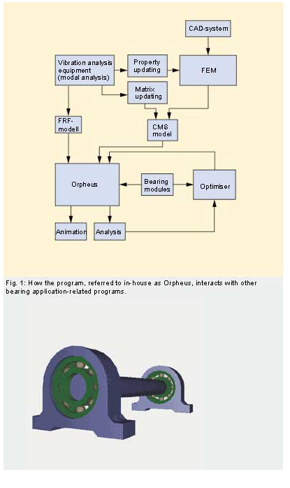
The program works in combination with other software modules (fig.1). Components such as housings and shafts can be modelled using the finite element method (FEM) in combination with the CMS method or experimental modal data. The component models are connected to the bearing models within the program, thus allowing simulation of the complete application. Model updating is an important feature that ensures that simulation of the models of individual components is as accurate as possible.
Computer animation, which allows vibration motions to be viewed, is also a useful feature that allows engineers to gain insight into the dynamic behaviour of the application. In order to compare different design variations, a proper analysis tool is necessary, delivering the appropriate data for decision making. Such a design process can be automated by feeding the results of analyses into an optimisation routine for use with bearings, shafts and housings.
Parametrically excited vibrations
A rolling bearing acts not only as a vibration transmitter but also as a generator. The rotation of the rolling elements inevitably reveals errors in the bearing components. This leads to a variation of the deflection in the contact, thereby generating vibrations. Vibrations also occur in a bearing with perfectly shaped components caused by the rotation of the rolling element set. In particular, significant parametrically excited vibrations can be expected when the various rolling elements are loaded and unloaded during a revolution of the cage.
A shaft having a diameter of 45 mm and a length of 500 mm illustrates a typical example (fig.2). It is supported by two deep groove ball bearings 6309 mounted in two plummer block housings. The shaft is loaded by a radial static load of 10,000 N and is rotating at 3,000 r/min.
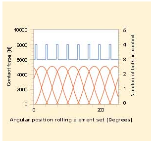
Not all rolling elements are loaded even under relatively high radial load because of the radial clearance in the bearing. The number of elements carrying the load varies between three and four during a single cage revolution. In (fig. 3), the lower lines indicate the force in the outer ring contact for the individual rolling elements (in this case balls) as a function of the angular position of the cage. The upper dotted line indicates the number of loaded balls.
As the number of rolling elements in contact increases or decreases, the properties of the bearing in terms of stiffness and damping change and cause parametrically excited vibrations. The time signal and spectrum of the vibrations (fig. 4) shows that the former is periodic, with a cycle time of 6.5 ms. This period is equal to the time between the passage of two consecutive balls. The inverse is called the ball pass frequency and can be seen as the heart beat frequency of the bearing. This frequency shows up clearly in the spectrum, where the ball pass frequency (153 Hz) and many higher harmonics can be recognised.
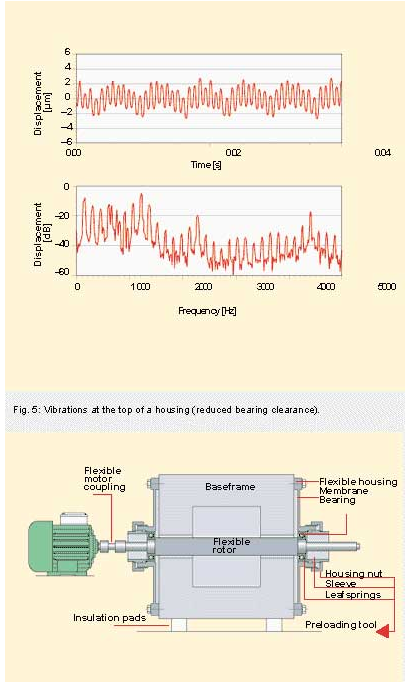
When the balls enter or leave the loaded zone, the sudden change in stiffness causes a high number of harmonics in the spectrum. It is possible to reduce parametrically excited vibrations by making the entrance of the balls into the loaded zone smoother, i.e. by increasing the angular width of the zone and thus the number of balls in contact. This can be achieved by reducing the radial clearance of the bearing from, say, 30 to 10 µm (fig. 5).
Validating the program
A special test rig was built to validate the program. This allowed bearing vibration generation and transmission to be investigated in detail. The test rig was designed to have its first eigen frequency well above 4 kHz. This meant that the dynamic behaviour of the bearing could be studied over a wide frequency range without any significant influence of the test rig dynamics. The test rig (fig. 6) consists of a massive steel block with several openings that provide access for instrumentation and mounting of rotor and bearings. Arbitrary end shields to hold the bearings can be mounted, including those used in real applications. The joints had to be designed and manufactured carefully in order to achieve the necessary stiffness of the assembly. Bearing preload and misalignment can be controlled. Rotor speeds up to 30,000 r/min are possible. Instrumentation can measure the vibration modes of the rotor shaft. A piezoelectric rotating unbalance device can excite the shaft into well–defined vibrations.
The in–house software has been used to answer a variety of questions. It has been used to explain, for example, the different vibration levels of an application when using bearings of nominally the same type, such as deep groove ball bearings 6202. It can determine whether the differences are due to differences in manufacturing accuracy or to different internal design and mounting. Alternatively, a customer may require vibration reduction over a certain frequency range and under specified application conditions. This was the case with an electric motor application (fig. 7). The motor has two deep groove ball bearings. A reduction in the frequency range 5–8 kHz was required, with no changes allowed to the motor itself. After some global vibration tests and a running mode analysis, the possible role of the two bearings in the motor’s dynamic behaviour was obtained.
Bearing vibration generation and transmission were distinguished. Repeatability and reproducibility of the measurements were checked. Finite element models of the end shields of the motor were obtained from the motor manufacturer. A rotor dynamic model was built for the rotor from design drawings. With sufficient agreement between the calculated and measured dynamic behaviour incorporating realistic raceway waviness profiles, design and installation modifications were calculated involving the bearing clearance, preload and osculation. The total number of degrees of freedom of the original FEM models was 43,363. After reduction by
the CMS technique, the calculations were performed with 83 degrees of freedom.
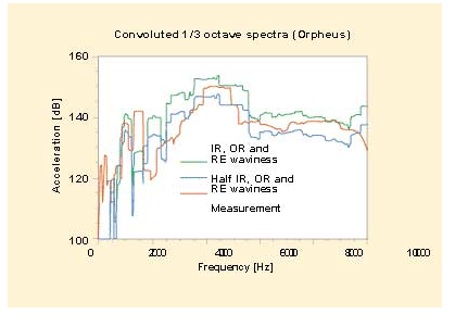
The targeted frequency range of 5–8 kHz showed a fair agreement between measurements and simulations (fig. 8). As the waviness is not known exactly, calculations were carried out for two different levels. The result of design optimisation was a reduction of preload. Furthermore, an increase of the internal clearance as well as a loosening of the outer ring osculation were necessary to achieve the reduction in vibrations over this range.
The program fills a gap that was left in the simulation of rotating machinery. Up to now, extremely simple assumptions had to be made relating to the dynamic properties of rolling bearings. The correlation of calculations against test data indicates that this new program will make a considerable contribution to developing bearing solutions with reduced noise and vibration.
Teun Zandbergen and Gerrit van Nijen
SKF Engineering and Research Centre (ERC),
Nieuwegein, the Netherlands


