Simulation of dynamic behavior of rolling bearings
The mechanisms above can be used individually or combined in any way. The functions for prescribed motion and load are functions of time.
Computer simulation techniques have been developed to focus on the dynamic behavior of rolling bearings. This can provide insights into phenomena that affect their performance in applications.Rolling bearings have been common machine elements for more than 100 years. During this time, vast experience has been accumulated about their steady-state behavior, such as their load-carrying capacity. Fatigue-life predictions have also been refined to handle clean and contaminated bearings. The understanding of the dynamic behavior of rolling bearings has not reached the same level of maturity. Yet most phenomena that occur in rolling bearings, both under normal and unacceptable operations, are dynamic by nature.
These dynamic phenomena need to be studied using dynamic tools. One such tool is BEAST, or “bearing simulation tool,” developed by SKF. BEAST is based on multibody techniques, with special focus on contact problems. It allows for studies of dynamic behavior of all bearing components to be carried out under general loading conditions. This includes looking at the forces on, and motions of, the cage, skew and tilt behavior of rollers and the skidding of balls. A description of the most important aspects of the BEAST model, and some examples of comparisons with experiments, is the focus of this article.
Complete bearing model
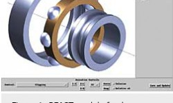
Rolling bearings are machine elements that provide high precision and load-carrying capacity, together with low-friction torque, vibration and noise emission. Figure 1 shows the major elements of a rolling bearing: an inner ring, an outer ring and a set of rolling elements (balls or rollers). Additionally, most rolling bearings have a cage (or cages) and a few have a guide ring.
BEAST is specifically designed to simulate the behavior of complete bearings, including cages, of all types of rolling bearings. Earlier versions of rolling-bearing simulation codes usually either leave out the cage or describe it in a very basic way, such as through two-dimensional models. BEAST, however, is a fully three-dimensional model, and no assumptions are made as to the static or dynamic behavior of the bearing components. Boundary conditions and applied loads can be given in an arbitrary way and the geometric description is very general, which is important especially for the cage.
Simulation model
A bearing is modelled as a multibody system. Bearing simulations involve the simultaneous solution of Newton’s equations of motion for each body in the bearing. Efficient and accurate contact calculation is thus the most important component in a bearing-simulation tool. Accurate contact-force calculations require a detailed geometric description of the contacting surfaces in the bearing, since features of the order of 0.1 micrometer may result in quite large differences in bearing performance, such as roller stability or contact-pressure distributions. Modelling the effect of various kinds of geometric imperfections is also of great interest. Local geometrical deviations can be specified. The effects of small-scale geometric variations such as surface roughness are taken care of in the tribology model.
Contact-force calculations
The contact-force model is the most important part of a rolling-bearing simulation model. Considerable demands are put on the contact model when it comes to calculation speed, generality, stability and accuracy. The elastic contact model in BEAST includes three-dimensional elastic effects of arbitrary geometry and truncation. The model has been verified against Finite Element Method (FEM) models and experiments, and gives an exact solution for Hertzian contacts.
The influence of lubrication is based on an elasto-hydrodynamic lubrication (EHL) contact model. It uses the pressure-viscosity relationship developed by Roelands and compressible oil. Run-time EHL calculations are still far too slow for a simulation program. Formulae for central film thickness, pressure moments and pressure distribution have, therefore, been derived from a large number of EHL calculations for a wide range of conditions.
In a rolling bearing, the lubrication regimen may vary from boundary lubrication to fully separated surfaces (EHL). For the separation parameter, a specific film thickness, L=h/s, is used, where h is the calculated film thickness and s is the root mean square of the surface roughness of the two contacting surfaces.
In the fully separated regimen, the shear stress is calculated with a smoothed variant of the limiting shear stress model. In the boundary regimen, a coefficient of friction, provided by the user, is used. A formula by Steinert is currently used for the transition between fully separated and boundary conditions.
The user defines the amount of oil in the contact by giving the combined oil-layer thickness of the two contacting surfaces. During film-thickness calculation, the degree of starvation will automatically be determined.
Other topological effects, such as roughness orientation due to the grinding direction, may also influence the film build-up and, consequently, the traction. Until this phenomenon is better understood, a factor that is tuned to specific applications can be used.
Semi-empirical models for material and squeeze damping are used for all contacts. The models are calibrated against experiments with balls bouncing on plates made of various materials and with different oil-layer thicknesses.
Boundary conditions
A rolling bearing is always part of a machine. The connection between the bearing and the machine, i.e., the boundary conditions of the bearing, are as important as the internal modelling of the bearing. BEAST provides versatile models for the connections in order to make realistic modelling of real applications possible.
Connections between bodies can be described independently, in six degrees of freedom: three linear motions (x, y, z) and three rotations around the same axes. Several types of connections are available:
- linear spring and damper, where the coefficients can have any value, including zero;
- simple bearing models with non-linear stiffness, clearance and damping;
- arbitrary load functions; and
- arbitrary functions of prescribed motions.
The mechanisms above can be used individually or combined in any way. The functions for prescribed motion and load are functions of time.
Output data
BEAST makes a very detailed analysis of the bearing behavior and, consequently, produces considerable output data. The principal data relate to the movements of all bearing components, the contact forces between the components, and the forces with the environment. Additionally, detailed data from the contacts are produced, e.g., power loss, film thickness, pressure distribution, slip-speed distribution and wear.
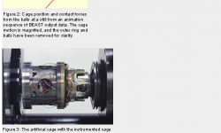
The output data can be studied in several ways. It is often natural to start by looking at an animation of the bearing components, which motions can be magnified for clarity. Force or velocity vectors can be added to the animation (see Fig. 2). Some parameters such as contact pressure or slip velocities can be displayed as three-dimensional images on the bodies or on parametric surfaces (Fig. 7) All output data can also be studied in great detail and flexibly, using two-dimensional graphs as shown in Fig. 4.
Examples of rolling-bearing simulations
A number of verification tests to confirm rolling-bearing simulations have been carried out in a test rig called CATRIONA. In the first test series, forces between the cage and the balls were measured. The second test series looked at the cage motion.
The CATRIONA test rig consists of a high-precision hydrostatic spindle on which the inner ring of the bearing is mounted. The outer ring is mounted in a yoke onto which pneumatic force actuators are attached, one in the radial direction and three in the axial direction. This arrangement makes various load combinations possible. The tests were conducted on a deep groove ball bearing of type 6309.
BEAST simulations of selected tests were carried out. The geometry, materials used and loading conditions were all described to the BEAST program so that they would represent as closely as possible the real test conditions. For some of the individual loads and inner-ring speeds, see Table 1.
Cage pocket forces
The cage pocket forces were measured on a special cage (Fig. 3) that was mounted on an aerostatic spindle with low friction and then inserted into the bearing. The cage pocket forces were measured with strain gauges. The cage bars on which the forces were measured were split, both to increase the signal from the strain gauges and to separate the force signal from the two sides of the cage bar. By having the cage mounted on a spindle, the cage position could be controlled and strain gauge amplifiers could be placed close to the strain gauges.
The BEAST model of the cage included the inertia of the aerostatic spindle as well as its stiffness and damping values. The spindle also exerted a braking torque on the cage, the value of which was calculated approximately. The breaking torque was so small that it could not be determined from the measurements, and the effect on the cage/pocket forces was not noticeable when the torque was varied in the simulations.
During testing, a large number of combinations of load type (radial/axial/combined), load magnitude and inner-ring speeds were tested. Of these tests, the ones given in Table 1 are reported here.
Pocket forces at pure radial load
For the radial load condition, the experimental cases R1 and R5 are shown. In these two cases, the bearing is loaded with a pure radial load of 1,000 N. The only difference between the two cases is the rotational speed of the inner ring.
With a pure radial load there will be one well-defined loaded zone for the balls. Since the radial load is acting upwards on the outer ring, the loaded zone will be at the bottom of the bearing.
Test Case R1
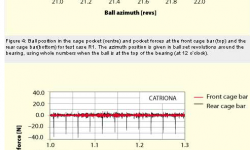
Figure 4 shows in detail what is happening to the ball during one revolution in test case R1. The bearing is running at 600 r/min under a radial load of 1 kN. The characteristic behavior of this test case is a series of declining impact forces on both the front and the rear cage bars. The ball starts at the top in the bearing. As it moves “downhill,” it accelerates due to gravity and bounces on the front cage bar. This happens because the speed is low and the ball is still unloaded. As it moves into the loaded zone, the ball is still close to the front cage bar, since the loaded balls determine the cage speed. After the loaded zone, the ball looses speed, both due to gravity and due to other losses as it rolls on the outer ring. The speed difference between the ball and the cage is therefore larger, giving a somewhat larger impact force in the bounces, compared to the front cage bar. This effect is not so apparent in the measurements.
Test case R5
Figure 5 shows calculated and measured results for test case R5, with an inner-ring speed of 6,000 r/min. At this speed, the balls no longer have time to bounce. The impacts now basically only occur on the rear cage bar, since at this position the speed difference between the balls and the cage is largest. The timing of the force peaks is good, and the calculated force magnitudes are close to the measured ones.
Pocket force at misaligned load
If a misalignment around the horizontal axis is applied (test case M24, 3,000 r/min), quite a different force pattern is found. Here the forces are not just impacts, but of longer duration (see Fig. 6). This is due to the fact that the balls are loaded differently at various positions in the bearing. This gives them a different tangential speed. If the difference in tangential position, due to the difference in speed, is larger than the available cage pocket clearance, the balls will come “into conflict” with the cage, i.e., the loaded balls will be in contact with the cage for longer periods of time.
The ball contacts the cage twice per ball set revolution – once at the front cage bar and once at the rear. The force peaks start with an impact but are, to the greatest extent, friction-driven. The impact peaks are not as visible in the measured cases, due to the elasticity of the real cage bars.
The difference in the loading of the balls can also be seen in Fig. 7, where the pressure distribution between the balls and the inner ring is shown. The inner-ring race segment is plotted as a parametric surface, with the circumferential direction running in the bottom-left to top-right direction. The pressure distributions vary both in size and in position, due to the misaligned load.
Cage movement
In a second test series in CATRIONA, the movement of a “normal” cage was studied. The cage motion was measured with three proximity sensors in the axial direction and four sensors in the radial directions. The motion of the cage in the plane of the bearing is of most interest, and that is where the evaluations were concentrated.
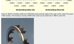
The cage was a standard polymer (glass fibre reinforced polyamide 6,6) snap cage. The only modification was a thin steel collar mounted on the cage backbone, (see Fig. 8) in order to obtain a good counter surface for the proximity sensors.
Similar to the cage-force tests, a number of combinations of load type (radial/axial/combined), load magnitude and inner-ring speeds were tested.
Cage movements at pure axial load
At pure axial load (test case A10), all the balls are equally loaded and run at the same speed. This usually produces a steady whirl motion of the cage (see Figure 9). Due to start-up conditions such as the influence of gravity, the balls will be in different positions relative to each other. This mechanism, which has a stochastic component, may give different whirl radii and center positions. At normal cage clearances and rotational speeds, the centrifugal force is smaller than the gravitational force. For ball-guided cages, the cage normally whirls with the ball set speed. This may not be the case for ring-guided cages.
An example of the stochastic nature of the whirl radius was seen in the experiments, where two identical, axially loaded cases, which had different direction of rotation, gave two quite different whirl radii.
Conclusions
Rolling bearings cannot easily be modelled with accuracy with multipurpose, multibody dynamics software. The demands put on the speed and accuracy of the contact-force calculation models are too high.
SKF has developed a simulation program that meets these demands, in which parallel computing and the utilisation of a structured system of equations are used to further speed up the calculations.
The simulation tool is called BEAST, or “bearing simulation tool,” and it has been verified against several experiments, some of which have been discussed here. The examples here only show a small portion of the total application range of BEAST.
BEAST is used by SKF engineers to increase their know-how of bearing dynamics, to speed up the development process and to give advanced application support to SKF’s customers.
Lars-Erik Stacke and Dag Fritzson,
SKF Group Manufacturing Development Center, Göteborg, Sweden,
and Bengt Rydell, SKF Engineering & Research Center B.V. (ERC), Nieuwegein,
the Netherlands.


