Material insights: Case-carburized bearings undergoing standing contact loading
Study enhances understanding and offers practical method for assessing the performance of case carburized bearings.
Optimal carburized case depth for bearing performance
To enhance wear resistance and load-carrying capacity, the working contact surfaces of bearings undergo specific heat treatments. Depending on factors such as the bearing size and the steel grades utilized, components may undergo either through hardening or surface hardening. Through hardening is suitable for high-carbon steels, while low-carbon steels (< 0.25% carbon) require case hardening, achieved through processes such as carburizing. Surface induction hardening is another widely used method for medium-carbon steels.
Carburizing involves the diffusion of a carbon source into low-carbon steel at high temperatures, forming a hardened surface layer known as a “case” upon quenching. The load-carrying capacity of surface-hardened bearings depends on factors such as the hardening case depth and core strength. Bearing manufacturers must carefully select steel grades and ensure adequate case depth for specific applications. However, excessive case depth not only increases unnecessary manufacturing cost, but can also lead to potential cracking during hardening and undesirable effects such as intergranular oxidation and enlarged grains [1].
Core crushing [2, 3], a failure mode in surface-hardened bearings, arises from insufficient case depth or excessive contact loads or a combination of both. This failure involves the initiation and propagation of cracks within the core of the material beneath the hardened layer. The difference in hardness between the surface layer and the core contributes significantly to core crushing, as stresses from rolling contact may surpass the core’s static or fatigue strength. Studies by Alfredsson and Olsson [4] and Lai et al. [5] observed core crushing in surface-hardened samples subjected to standing contact fatigue (SCF) loading conditions. SCF is a test involving cyclic indenting of a specimen surface with a ball or roller. Numerical simulations [5] revealed that shallow case depths or excessive contact loads induce significant tensile residual stress at the transition zone between case and core, leading to lateral crack formation under SCF loading. Severe plasticity in the core weakens its support to the case layer, causing bending of the case layer and potential cracking if the stress limits are exceeded. Aside from core crushing, the static load-carrying capacity of surface-hardened bearings is indicated by plastic deformation under stationary contact loads. However, the static load rating defined in ISO 76 [6] does not consider surface-hardened bearings. Calculation methods [5] have been proposed for evaluating raceway plastic indentation in surface induction-hardened slewing bearings.
This article is based on a study that we published recently [7], aiming to characterize and model the material behaviour of case-carburized bearings under SCF conditions. By evaluating surface plastic indentation and the risk of core crushing, the research offers insights for design engineers and manufacturers, particularly in optimizing the performance of case-carburized bearings.
Numerical simulation and modelling
The interaction between a rolling element and the raceway surface in a case-carburized bearing ring is simulated using finite element analysis (FEA) with the ABAQUS commercial code. The simulation encompasses three contact types: point contact (PC), line contact (LC) and elliptical contact (EC).
Given our focus on understanding the material response to standing contact loads, the elastic-plastic behaviour of the material is crucial in the FE model. Describing the elastic-plastic deformation involves the stress-strain relation, typically derived from tensile or compressive tests. As material strength is intricately linked to hardness, we correlate the strength gradient in the carburized component to the hardness profile. By establishing stress-strain curves for the core structure and the hardened case structure through compression tests, we employ linear interpolation to approximate the stress-strain relation for material with any other hardness.
The FE model facilitates the assessment of surface plastic indentation and subsurface damage resulting from standing contact loads. Through a parametric study encompassing diverse loading conditions and hardness profiles, we derive empirical equations expressing raceway plastic deformation as a function of case depth, case and core hardness, rolling element diameter and contact pressure. Moreover, the study allows for establishing tolerance limits for subsurface damage in case-carburized bearing rings subjected to standing contact loading conditions.
Consider a component with uniform hardness, akin to through-hardening or the core structure before carburizing. Surface plastic indentation (δ) relates to maximum contact pressure (p0) and material yield strength (σy) as:
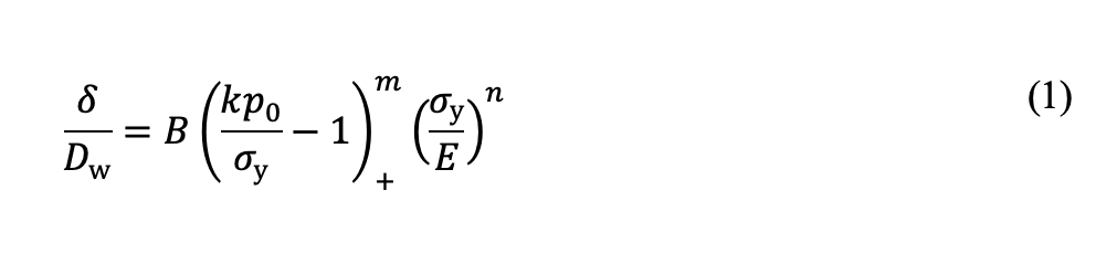
Here, Dw is the rolling element diameter and (…)+ denotes the McCauley bracket, setting the term to zero if the enclosed quantity is negative. Constant k, independent of materials, connects contact pressure p0 and maximum von Mises stress σvM (σvM = kp0). For point contact (PC), k = 0.62, and for line contact (LC), k = 0.56. Constants B, n, and m are material-specific.

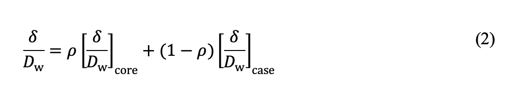
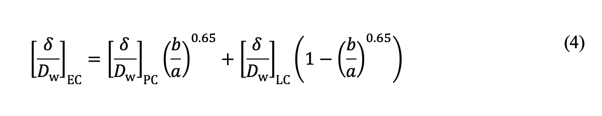
where [δ /Dw]case and [δ /Dw]core are plastic indentations for case and core materials, respectively, given by Eq. (1). the partitioning parameter ρ in the above equation is a function of the relative case depth hc /Dw and contact pressure:
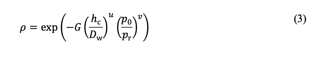
where pr is a reference pressure set to 1000 MPa. Constants G, u and v are determined by fitting Eq. (2) with Eq. (3) to plastic indentation data obtained from FE calculations, as illustrated in fig. 1. Note that the static load rating for through-hardened bearings is defined as the contact pressure that corresponds to a surface plastic indentation depth of 10-4Dw [6].
Elliptical contact plastic indentation [δ /Dw]EC results from interpolation based on the b /a ratio between solutions for point and line contacts:
From the FE analysis, we explore the material response regarding plasticity-induced residual stress. When the stress from a static load surpasses the yield strength of the core material, plastic flow occurs, leading to subsurface material damage in the form of residual stress. Fig. 2a illustrates a tensile residual stress zone in the case-core transient region resulting from a high-contact stress. A comparable residual stress pattern was identified in surface induction-hardened parts subjected to ball or roller indentation, as demonstrated in a previous study [5]. That study revealed that under SCF loading conditions, tensile residual stress may induce cracking or delamination at the case and core interface.
The expression for subsurface tensile residual stress due to standing contact loading, previously established [5], proves applicable to case-carburized components:
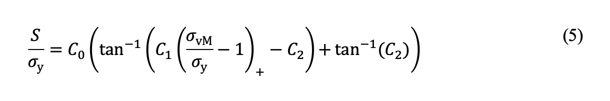
in which σy is the yield strength of the core material, σvM is the equivalent von Mises stress at a depth of hc from the surface or the depth at which the hardness is equal to HV550. C0, C1 and C2 are constants, which can be determined by fitting Eq. (5) to the FE results. It’s important to note that the von Mises stress here is evaluated using the Hertzian theory of elastic contact, representing the stress solution under the assumption of linear elasticity. Fig. 2b shows the tensile residual stresses as a function of the equivalent von Mises stress at a depth of hc from the surface for line contact and point contact, respectively. The critical stress, Sc, can be assessed using the principles of fracture mechanics and the El Haddad [8] approach to consider small crack effects, as detailed in our prior work [5].

Experiment and model verification
SCF tests were conducted on a flat specimen made of ASTM A534-18NiCrMo14-6. Two disc specimens underwent carburizing followed by hardening, resulting in two hardness profiles with case depths of 0.5 mm and 0.9 mm, respectively. The SCF testing employed a crowned roller indenter with a diameter of 10 mm and a crown radius of 98 mm, made of martensitically hardened ASTM A295-52100 steel. Strain gauges were affixed just outside the indented area to monitor strain changes during the tests. It has been established [4] that a sudden increase in strain indicates the onset of a lateral crack in the case-core transition zone, serving as evidence of core crushing failure under SCF loading conditions for a surface-hardened component.
Fig. 3a displays the measured plastic indentations in comparison with model predictions using Eqs. (1) – (4), showing good agreement between prediction and experiment.
For all tests on both discs at different loads, no indications of lateral crack development in the subsurface regions were observed from the strain gauge signals. Post-test metallographic investigation confirmed no lateral cracks in the subsurface regions of the tested discs. Fig. 3b presents all SCF tests grouped in Disc #1 and Disc #2, corresponding to two case depths. The critical load for core crushing, indicating the onset of a subsurface lateral crack, was calculated and plotted in Fig. 3b. The model prediction is considered plausible, as almost all experimental data points, indicating no core crushing, fall below the predicted critical loads. The only data point slightly higher than the predicted critical load suggests a conservative model prediction. Notably, the SCF tests on both discs involved extremely high loads in terms of nominal contact pressure. For instance, the highest load on Disc #1 corresponds to a Hertzian pressure of 7.1 GPa, while the maximum contact pressure for Disc #2 reached 7.7 GPa. Compared to surface induction-hardened components [5], the case-carburized steel in this study appears less susceptible to core crushing, attributed to its properties.

Static indentation tests were also performed on the raceway surface of a cylindrical roller bearing (CRB). The testing sample was a segment cut from the CRB inner ring made of case-carburized and hardened ASTM A534-18NiCrMo14-6 steel. Through-hardened cylindrical rollers of different diameters were used as indenters to obtain loading conditions with different relative case depths in terms of the hc / Dw ratio.
Fig. 4 shows the plastic indentations for two relative case depths, obtained from measurement and prediction using Eqs. (1) – (4), respectively. A rather good agreement is seen between the experiment and model prediction.

Concluding remarks
In conclusion, this study delved into the material response of case-carburized rings under SCF loading, employing a combination of numerical simulations and experimental investigations. By focusing on surface plastic indentation and subsurface core crushing, our finite element-based models accurately predicted material damage and deformation behaviour. Validation through SCF tests on both a carburized block and inner ring of a cylindrical roller bearing confirmed the model’s reliability. This work not only enhances understanding but also offers a practical method for assessing the performance of case-carburized bearings in standing contact conditions, with potential implications for optimizing design and durability in engineering applications.