Wear and surface fatigue in rolling bearings
Even with careful observation, measurement and monitoring, wear in rolling bearings is hard to predict. SKF has dedicated considerable research and analysis to the study of sliding and wear and their effect on bearing life.
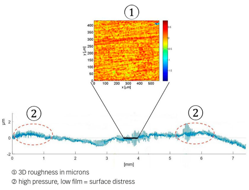
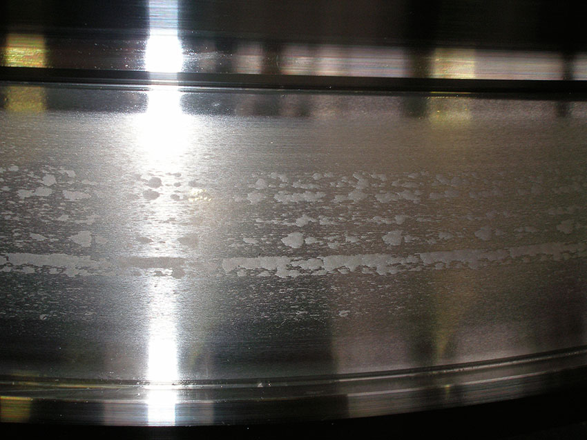
In some applications, rolling bearings can suffer a substantial loss of material (wear) due to lack of lubrication, the presence of abrasive particles, corrosion, oscillating rotation and other causes. Such wear can in turn have a detrimental effect on bearing operation, from the reduction of preload to potentially catastrophic effects. One common and perhaps unexpected consequence of uneven wear in the bearing raceways is the increasing possibility of surface fatigue. In some applications, it is not uncommon to see bands of surface distress or surface spalling along the raceways. This is associated with the possibility of raceway profile modification from uneven wear, which can give rise to stress concentration in the lines of high pressure and lower film thickness.
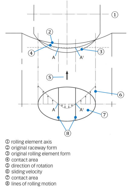
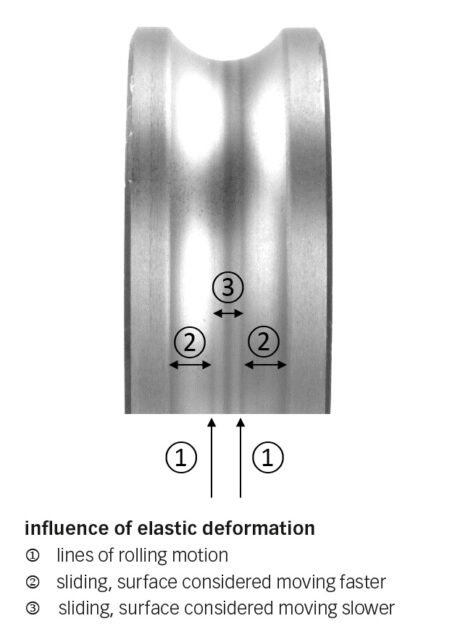
Any rolling bearing has some degree of sliding; this is normal. It is produced by the bearing internal geometry and/or the loading conditions. For example, a radial ball or roller bearing, perfectly radially loaded, will also have sliding (Heathcote slip) due to the rolling element/ring contact geometry and elastic deformation from load (figs. 4a and 4b). Since wear depends on sliding, in time (if the conditions are given right) it would be expected that the pure rolling bands (A and A1) will be the only zones where wear will not happen and therefore the only zones that will carry all the load in the contact.
The current paper will go a bit deeper into the main mechanisms of the potential wear-fatigue combination damage mode. The modelling and the experiments were carried out to understand it better and to shed some light on ways of prevention.
Modelling
Modelling wear
In [2], different wear models under lubricated conditions are discussed, and it is concluded that in all cases they can be represented by an Archard model [3], sometimes with a sophisticated wear coefficient model. In most cases the wear coefficient is an empirical factor based on experiments. Thus, the most general wear equation is:
V = wear volume [m3] in a certain time,
F = contact force [N],
H = current surface material hardness [Pa],
s = sliding distance [m] in a certain time.
The wear volume can be expressed as:
h = removed surface layer thickness [m] in a certain time,
As = sliding area [m2] in a certain time.
Thus, substituting (2) into (1) and considering that the contact mean pressure ![]() :
:
us = the local sliding speed [m/s]
u1 = the mean speed of the analysed surface [m/s]
l = the contact length along the sliding direction [m].
Notice that nearly all quantities are local (x,y.) Here also the hardness of the steel in the raceways and rolling elements will be assumed as constant. Equation (4) gives the local thickness of the worn layer removed at every over-rolling in a bearing contact.
Modelling the interaction wear-fatigue
To model the interaction wear/fatigue in bearings, a rolling contact fatigue (RCF) model needs to be applied at every over-rolling of the raceway with a previously modified profile (on both surfaces) due to wear; in this way both phenomena (wear and fatigue) interact. Every time that wear modifies the profile a new pressure distribution in the contact needs to be calculated for the fatigue model. This process reflects what happens in real life. However, it is very costly computationally speaking, considering that typical RCF lives can cover millions of over-rollings. Thus, there are simplifications that reduce substantially the computational cost:
- A dry contact calculation is applied rather than a full elastohydrodynamic lubrication (EHL) solution, avoiding in this case the solution of the lubrication problem by simply considering a (measured) fixed friction coefficient.
- Updating the profile resulting from wear every certain number of over-rollings, instead of updating it at every single over-rolling.
- Point number (2) has also as a consequence that the update of the contact calculation and the damage (fatigue) calculation can also be done at the same time as the update of the profile by wear, instead of at every single over-rolling.
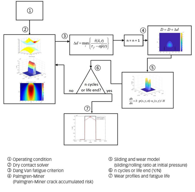
The flow chart of fig. 5 shows a summary of the calculation procedure. Notice that in this case the fatigue criterion of Dang Van [4] is used and the damage accumulation is done via the linear law of Palmgren-Miner [5,6]. But any other fatigue criterion and damage accumulation load could have been used, if the experiments would suggest that.
Experiments
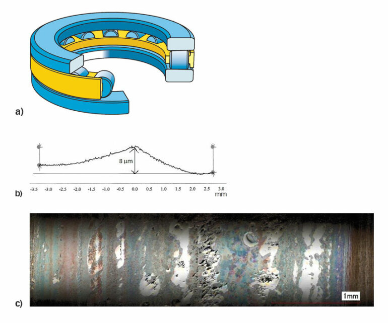
To validate the fatigue model, an endurance test was conducted using a cylindrical thrust roller bearing 81107 TN (fig. 6a), axially loaded with C/P = 6.5 and lubrication conditions given by a ![]() ≈ 0.5.
≈ 0.5.
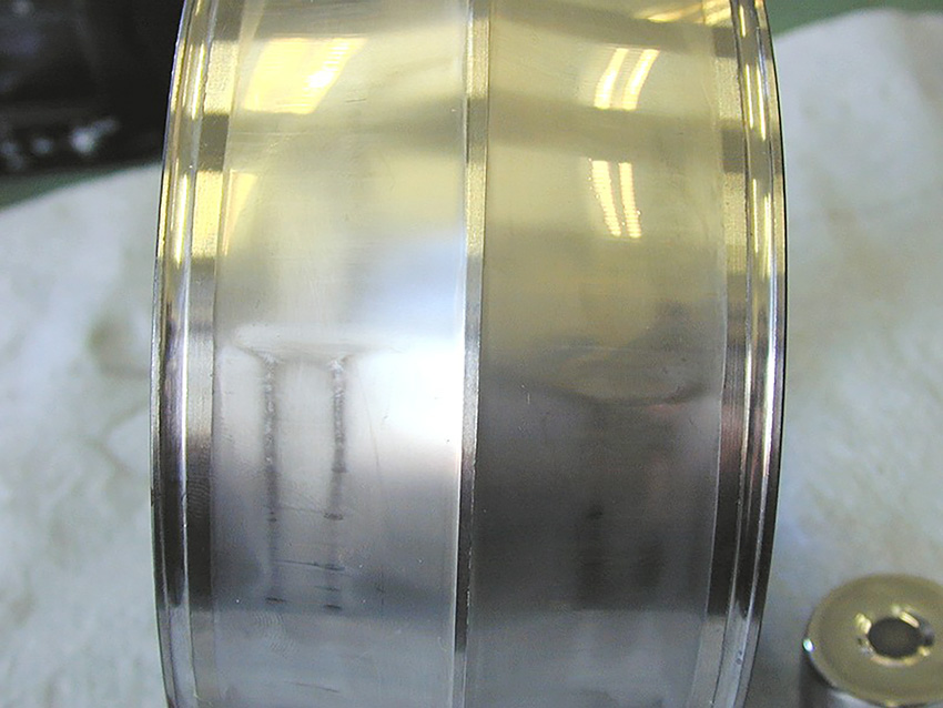
Prior to testing, an artificial profiling (fig. 6b) was made in the new bearings, as if they had been running under heavy wear conditions. During testing, some bearings failed, mainly due to roller damage (fig. 6c), so that the life model could be compared with the results from the short test. Exactly the same worn rollers and new washers were considered in the model of fig. 5; the results showed very good agreement with the lower bound limit of the measured L10 life, considering the Weibull statistics.
Results
In thrust cylindrical roller bearings the sliding varies linearly (decreases) from the two edges of the roller towards the pitch line, where sliding is zero (fig. 7). Towards the outside diameter of the bearing the roller will be the fastest surface, and towards the inside diameter it will be the slowest one. To illustrate the concurrent effects of wear and fatigue in a rolling bearing with variable sliding across the raceway, another thrust roller bearing case is considered with a larger bearing (81212 TN), as described in the data of Table 1.
Instead of updating the profiles for wear at every over-rolling, to save computational time without losing accuracy, it was found that the updates could be done every 15.5 million over-rollings on the roller. For the simulation, the same model represented as in fig. 5 is applied, including the Archard wear model of equation (4).
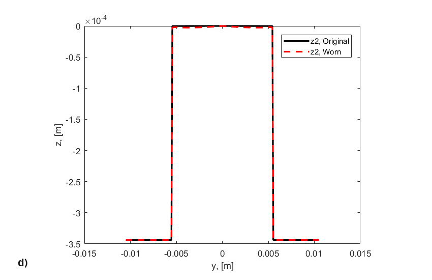
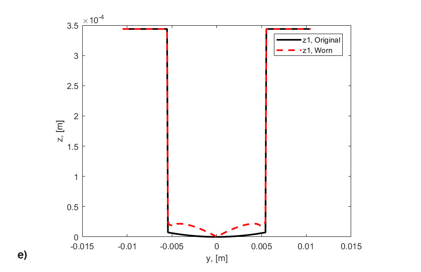
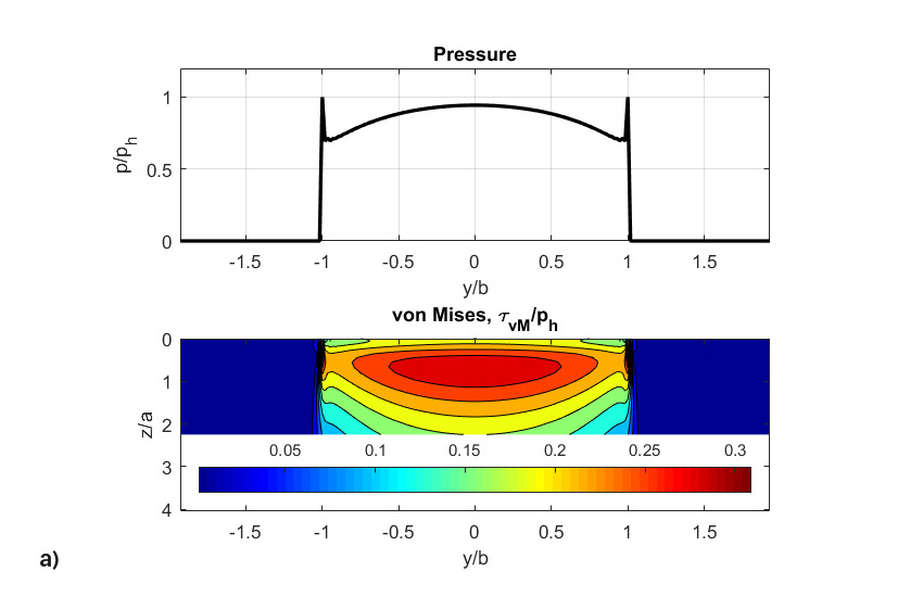
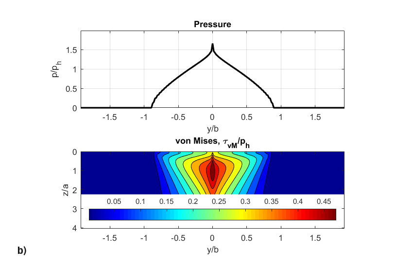
The results of the simulation are shown in fig. 8. The figure displays:
- the dimensionless pressures,
- von Mises shear stresses,
- the damage map,
- the original roller and washer profiles,
- the worn roller and washer profiles, corresponding to the time step of the end of the simulations.
It must be pointed out that the damage map reached a total damage value higher than 1 (crack initiation threshold) after only 31 million over-rollings. The results displayed in fig. 8 are related to the initial and final simulation steps. The initial pressure (fig. 8a) in the first over-rolling looks more or less Hertzian, but shows some edge-stress effect since a simple straight roller profile was used, instead of a proper profiled roller that avoids those edge stresses. From the results it is evident that the sliding is zero in the pitch line; also, the Archard wear model part of the simulation indicates zero wear in that location.
Indeed, wear is linked to the slip distribution across the raceway. Thus, wear will take place at an increased rate as one moves away from the pitch line of the raceway. Note that originally the contact pressure was nearly rectangular (fig. 8a), but as material is being removed from the two sides of the rolling contact the pressure is reduced in the areas of high sliding and is strongly augmented and concentrated in the area of zero sliding (pitch line), (fig. 8b). This increased pressure produces high stresses and fatigue at a faster rate until failure develops at the middle of the roller (fig. 8c). The simultaneous and concurrent effect of wear and fatigue can indeed accelerate the RCF spalling of the contact. This accelerated fatigue spalling is not related to frictional stress induced by sliding, but rather is the result of the modification of the original profile of the rolling bodies (figs. 8d and 8e) leading to a sharp rise in contact stress and localized lower film thickness.
Conclusions
From the modelling of the concurrent effects of abrasive wear and RCF, it is found that sliding might become an import-ant element in increasing the fatigue damage of a bearing. This requires the presence of abrasive particles and/or very poor lubrication conditions in the bearing. Non-uniform slip distribution within the Hertzian contact also contributes to the development of stress risers that significantly shorten the fatigue life expectancy of the bearing. Indeed, this seems to be the most significant mechanism by which Hertzian sliding might eventually reduce the RCF life of the bearing.
To reduce this risk the following recommendations are given:
- Make sure there is always adequate lubrication in the bearing, especially in large-size bearings with slow rotational or oscillating speed, bearings in the presence of large amounts of abrasive particles or bearings exposed to corrosion.
- Optimize sealing solutions; eventually use sealed/shielded bearings.
- Reduce solid and liquid contam-ination as much as possible.
- Avoid shock loads and vibrations that can substantially increase the nominal sliding conditions in the bearing.
- In the case of large-size bearings, if uneven wear is detected in time, remanufacture can be a cost-reduction aspect to be considered.
The author wants to thank Ralph Meeuwenoord for his kind support in the experimental phase of this project.






![Palmgren-Miner damage map after simulation for the same example of Table 1 with a wear coefficient of =0.5x10⁻¹¹ [s]](https://evolution.skf.com/wp-content/uploads/sites/5/2019/06/wear-and-surface-fatigue-in-rolling-bearings-fig8c-1.jpg)
