A better understanding of material imperfections
In SKF, research has continuously been carried out to better understand the effects of microstructure and pre-existing material imperfections on bearing performance. The presented work is fundamental for defining what features and related severity classes are critical for influencing bearing performance.
Nowadays, bearing failure due to rolling contact fatigue (RCF) is generally a rare occurrence, and the final achieved life of rolling bearings is usually in excess of the calculated rating life. There are instances, however, where in specific applications bearings may fail prematurely. Understanding bearing failure mechanisms is fundamental for continuous improvement of bearing performance, in response to the requirement for the ever-increasing power density with modern rolling bearing applications.
The reliability of rolling bearings used in various applications obeys the weakest link principle, i.e., failure is a result of breakage of the weakest link inside the concerned system. Under poor lubrication conditions, bearing failure could be due to surface damage in the form of surface distress or wear. Otherwise, the weakest link could exist in the subsurface region. This is because the shear stress resulting from Hertzian contact reaches the maximum at a certain depth below the raceway surface. Furthermore, like most high-strength materials, bearing steels in general can suffer from lack of damage tolerance in the form of sensitivity to pre-existing material imperfections such as non-metallic inclusions as a by-product of steel-making processes.
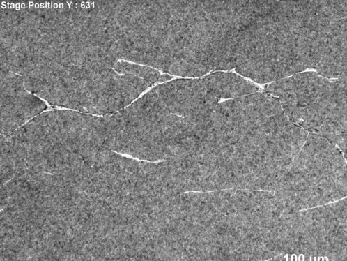
Metallographic investigations on RCF-tested samples indicate that the so-called butterflies often develop from non-metallic inclusions. The butterfly seen from a nital-etched sample with light optical microscopy shows a pair of cracks emanating from an inclusion that are decorated with a white etching area, as shown in fig. 1. The white etching area is the altered microstructure resulting from rubbing between the crack faces [1, 2]. Under rolling contact loading, the crack may propagate and eventually break to the raceway surface, leading to surface spalling.

Material imperfections in RCF
Rolling contact on bearing raceway surfaces results in cyclic stresses that extend from surface to subsurface. Owing to the stress raising effect, cracks can be initiated from inclusions even under a contact pressure lower than the so-called elastic shakedown limit, i.e., a contact pressure below which the overall material, except for the regions in the vicinity of inclusions, behaves elastically. As depicted by fig. 2, the damage process involves three stages that may lead eventually to spalling of the bearing raceway surface.

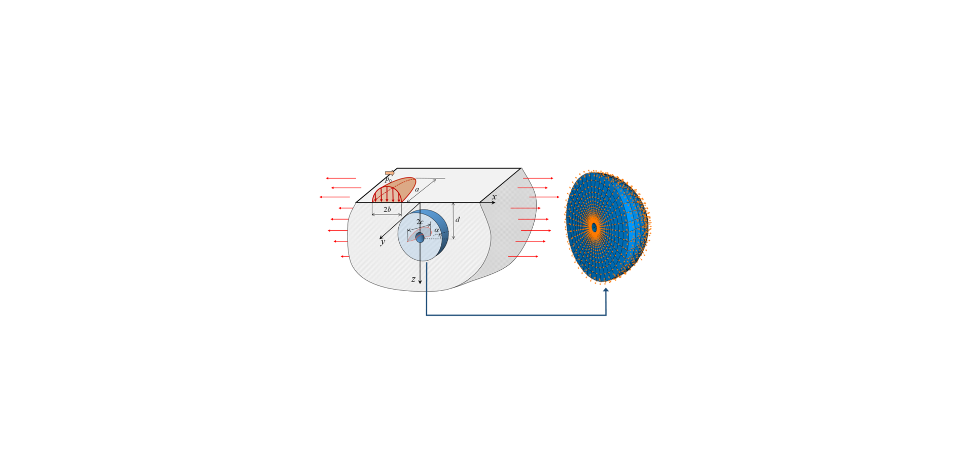
A new modelling methodology has been developed that combines FEM with an analytical solution of a half-space subjected to surface loading. As illustrated in fig. 3, a layer of material surrounding the defect is modelled by FEM, whereas the subsurface stressing and deformation arising from rolling contact are “transmitted” by the boundary nodes, at which the displacements are prescribed using the analytical half-space solution [3].
Different types of inclusions in terms of composition or morphology, and the condition of bonding between inclusions and the steel matrix, have been considered. The FE simulation also incorporates the elastic-plastic behaviour of bearing steels to account for the localized plasticity.

Fig. 4 shows the calculated stress raising factors of several material imperfections under RCF, including soft and hard particles and a pore. The particles are considered as elastic solids with a stiffness different from that of the steel matrix. Fig. 4 also displays the von Mises stress distribution near each of the inclusions. The fully bonded inclusion has a relatively low stress raising factor. A fully bonded soft particle has a higher stress raising factor than that of a fully bonded hard inclusion. The stress raising factor increases with the extent of de-bonding between the inclusion and the steel matrix. A pore is the extreme case that has the highest stress raising factor.
The stress concentration near an inclusion can cause local plasticity of the steel, which induces a localized tensile residual stress. The tensile residual stress, together with other components of the local stress near the inclusion, may cause crack initiation and initial crack propagation, i.e., the Stage-A fatigue damage indicated in fig. 2. The stress raising severity shown in fig. 4 indicates the harmfulness of different inclusions. Titanium nitride particles, which are normally well bonded with the bearing steel matrix, have been found much less harmful than aluminium oxide inclusions, which are also hard particles but have poor bonding with, even de-bonded from, the steel matrix.

Under a specified contact pressure, initiation of a crack from an inclusion depends primarily on the local stress near the inclusion. In other words, crack initiation is governed by the type but not the size of the inclusion, since the stress raising factor is independent of the inclusion size. However, a crack initiated from an inclusion will not always develop to form a spall. Under certain circumstances, the crack may be permanently arrested.
Fatigue crack growth is analysed within the framework of fracture mechanics. The driving force for fatigue crack growth can be calculated considering the sizes of the crack and inclusion of specific type, and the subsurface stress resulting Hertzian contact and superimposed stresses such as residual stresses, structural and/or hoop stresses, as indicated in fig. 3. If the driving force exceeds a certain threshold value, the crack will propagate and lead to failure. Otherwise, the crack will be arrested. The higher the driving force, the faster a crack propagates.
Consider, for example, a spherical inclusion of radius R, with an annular crack, length l, as indicated in fig. 5. The driving force is proportional to p0 √(R + l), with p0 being the contact pressure. This means that the driving force increases with the contact pressure. Under a specified p0, the size of the inclusion, R, governs the crack growth speed, especially during Stage-A where l is much smaller than R. The influence of the inclusion diminishes when the crack propagates away from the inclusion.

Finite element analysis has been performed to simulate propagation of a 3D crack from an ellipsoidal pore representing a de-bonded inclusion under RCF. The simulated crack propagation, as shown in fig. 6a, was compared to the crack configuration observed from RCF experiments. A qualitative agreement is found between the prediction and experiment.
The Stage-B crack propagation is primarily driven by the alternating shear stress resulting from rolling contact, which will sooner or later lead to the Stage-C crack propagation, i.e., crack branching due to an alternating tensile-compressive stress zone in the vicinity of the crack tip, as shown in fig. 6b. There exists a competition between the shearing-mode coplanar crack growth and the tensile-mode crack branching. The occurrence of crack branching may be affected by the superimposed stresses. A tensile stress promotes crack branching and may reduce fatigue life. A compressive stress is beneficial as it tends to suppress crack branching.

Fig. 7 shows the driving force for crack propagation from a spherical inclusion as a function of crack orientation, considering a contact pressure of 2.5 GPa and different levels of superimposed stresses. The driving forces for cracks of different orientation were evaluated. It can be seen from fig. 7 that in the absence of superimposed stresses, the maximum driving force corresponds to a crack orientation of 45°. If a compressive stress of 200 MPa is applied, the driving force curve reaches its peak at an angle of 30°; if a tensile stress of 200 MPa is applied, however, the crack orientation at which the driving force attains the maximum is increased to 57°. It can be said that a tensile stress may speed up crack propagation and tends to drive crack growth towards a steep angle, whereas a compressive stress may retard crack growth and tends to lead crack propagation towards a horizontal direction.

Significance from engineering perspective
The research on the fatigue mechanisms has resulted in the identification of one of the root causes for bearing premature failure [2]. Bearing premature failure characterized by white etching cracks (WECs) and axial cracks has been successfully reproduced in lab tests, in which the inner ring of a cylindrical roller bearing was mounted on a sleeve shaft with artificially introduced waviness. It was demonstrated by FE simulation that bearing seat form deviation such as waviness can result in tensile stresses near the raceway of the inner ring, which, if exceeding a certain limit, can weaken the material and, in combination with Hertzian stress, result in early initiation and accelerated growth of cracks from the pre-existing material imperfections, leading to premature failure of the bearing.
Furthermore, metallographic inspection using small-step serial sectioning of the tested rings indicated that WECs commonly found in prematurely failed bearings can be initiated from subsurface inclusions, as indicated in fig. 8. A similar conclusion was drawn from an independent research reported in [4]. The significance of this finding is the clarification relative to the origin of WECs. It can be said that a WEC is in essence a subsurface crack such as a butterfly, which can be initiated from a stress raiser, but has grown into the advanced stage. Repeated rubbing between crack surfaces under RCF causes gradual microstructural alteration that leads to formation of the white etching areas (WEAs) near the crack surfaces. Therefore, WEC or WEA is not the cause for the bearing premature failure, but a symptom of advanced RCF damage.

The tolerance limits for material imperfections can be established by virtue of a generalized Kitagawa diagram that, as illustrated in fig. 9, relates the fatigue limit in terms of the maximum contact pressure limit, to the defect size. When the defect becomes vanishingly small, the curve approaches the intrinsic fatigue limit of the matrix material. For large defects, the fatigue limit can be determined by the threshold condition for the onset of fatigue crack growth, i.e., the asymptote with a constant slope of µm, the value of which depends on the type of defect.

The original Kitagawa [6] diagram was proposed for the crack-like defects where m = 0.5. The generalized Kitagawa diagram can be applied for different materials and various types of defects. For example, it has been used to establish the tolerance limit for the missing-material defects on the surface of silicon nitride balls for hybrid bearings [6]. For this type of defect, m is 0.46.
Based on the description of fatigue crack initiation and propagation from subsurface inclusions, a model has been developed to predict the very high cycle fatigue (VHCF) strength and fatigue limit of bearing steels [7]. It was demonstrated [8] that the predicted fatigue limits and the VHCF testing data correlate well with the fatigue limit value set in the ISO 281:2007 standard for life rating of rolling bearings can be established.
Summary
Research on fatigue mechanisms is fundamental for the advancement of bearing technology to cope with the challenges from demanding applications. The presented work demonstrates that improved understanding of material imperfections and their effects on bearing performance shed new light on some problems where potential solutions can be developed to reduce bearing premature failure rate. Furthermore, the tolerance limits for material imperfections can be established.