New test methods on ceramic rolling elements
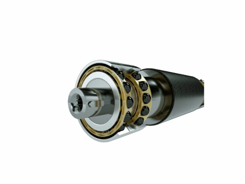
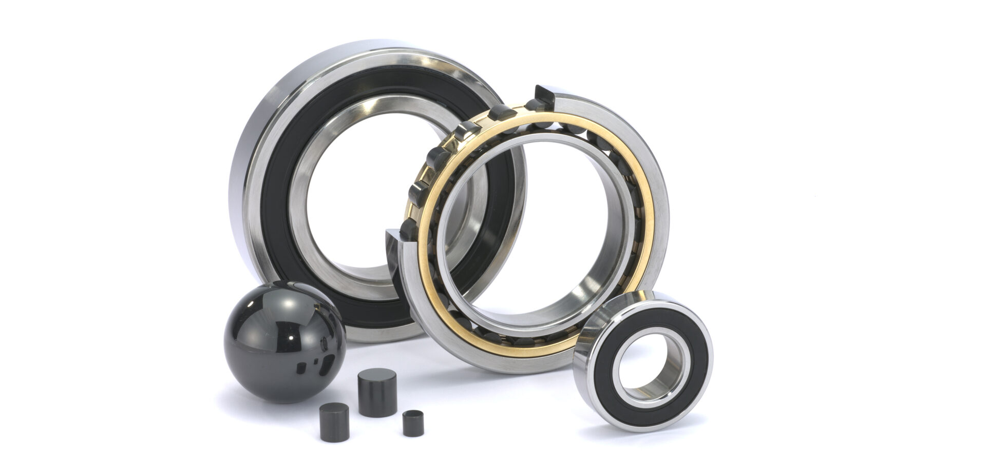
Certain highly demanding applications are best served with bearings that constitute a combination of steel rings with ceramic rolling elements, called hybrid bearings. The ceramic material, bearing-grade silicon nitride, is unlike common household ceramics; it exhibits very high hardness, toughness and strength, material properties that are critical for performance. SKF material specifications also include tight tolerances.
For the manufacture of silicon nitride balls and rollers for hybrid bearings, different processing routes lead to different microstructures and therefore to different mechanical properties [1]. This makes it necessary to perform testing on the individual balls or rollers to make sure that the minimum properties on strength, fracture toughness and microstructure requirements are fulfilled on the actual bearing component and not only on special bar samples prepared for bending tests.
In this article, different new methods for testing specific ceramic material properties are presented. These are being developed at SKF together with research partners and are already partially used for production support and defined in international standards. The goal is always to create helpful data to predict and ensure perform-ance of ceramic components in hybrid bearings.
Bulk ceramic scratch test
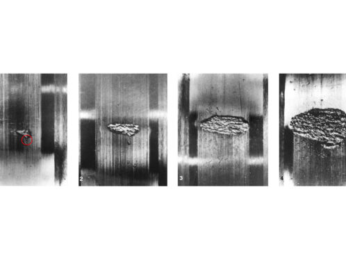
Different material grades of silicon nitride have been shown to feature distinct differences in grindability, crack nucleation and crack propagation. It is possible to employ a scratch testing device in order to systematically investigate the effects of sliding wear on silicon nitride materials. Historically, scratch testing was developed for testing adhesion of coatings, but it has also found applications in bulk testing. In this test, a geometrically well-defined diamond tip is guided with a defined speed in the 1–20 mm/s range across a surface with linearly increasing load. This leaves a track that can be evaluated under the microscope. The set-up is shown in fig. 1 and examples of scratches in fig. 2.
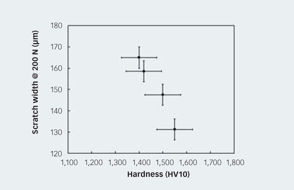
During loading, elliptical cracks are formed underneath the indenter. During unloading, lateral cracks form from relaxation of stresses in the contact zone. At a certain load level cracks appear, and these become longer with increasing load. At the higher load levels chipping will start. A number of material properties are known to affect this sliding wear behaviour: Hardness, phase transformation, elasticity, crack propagation resistance, friction, humidity, lubrication and repeated sliding play a role in the appearance of the track [2–4]. At the same time, this indentation of a defined tip with a specified load is similar to a typical hardness test as evidenced by the correlation between scratch width and hardness, shown in fig. 3.
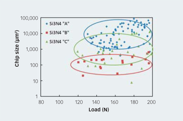
An important factor for successful and effective implementation of a new material is its grindability. This is a general term that encompasses material removal rate, chipping, grinding force, surface finish, tolerances and subsurface integrity [4]. Statistical evaluation of different silicon nitride materials by scratch testing enables classifying them according to their average chip size as a function of applied load at the diamond tip, as shown in fig. 4. This correlates well with grinding parameters such as pressure and speed.
Quasi-static fracture resistance test
For finished balls, a first approach done in the bearing industry is a simple crush test of two or three balls on top of each other. This gave a very rough estimate of a “static load rating”. The material resistance to cracks and Hertzian contact damage was tested by indentations with tungsten carbide spheres or by doing impact strength testing.
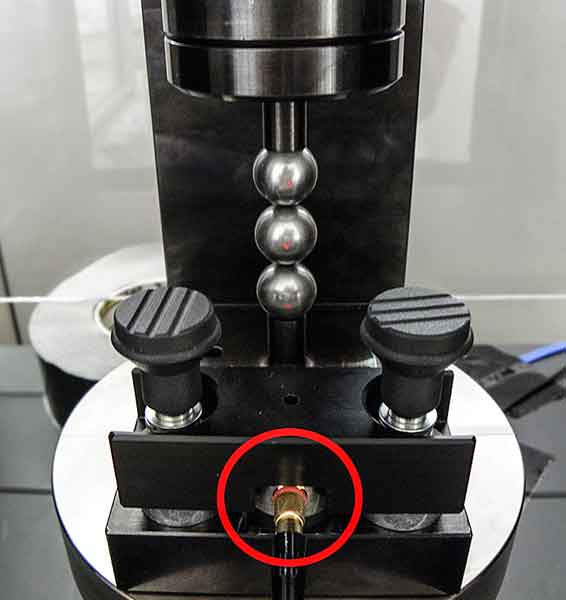
Using modern tools and data analysis, ceramic brittle fracture can be evaluated on ceramic balls, a method now in development at SKF. Three ceramic balls are lined up in a mechanical load cell as shown in fig. 5. Compressive load is increased slowly and linearly while measuring deformation and acoustic emission. Similar tests have been carried out earlier with a focus on crack formation analysis [5].
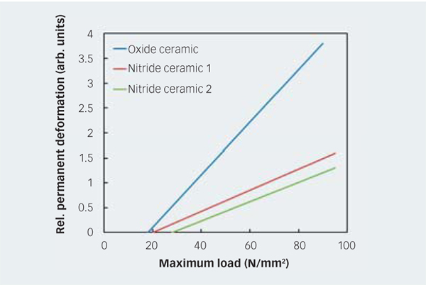
It is found that the dependency of permanent plastic deformation as a function of maximum load is close to linear and characteristic for different classes of ceramic materials (fig. 6). Additionally, the minimum load for permanent plastic deformation and the critical load for crack formation (from analysis of acoustic emission signal) permit ranking of different material grades of the same chemical composition and correlate well with strength and impact resistance.
Notched ball and notched roller test
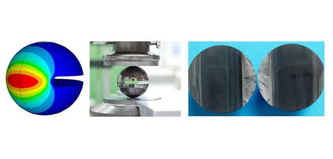
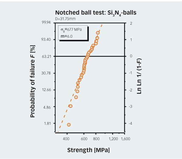
Strength, as a central material property, is traditionally measured on specially manufactured bending bars. This can be problematic since these bars have to be cut and finished in a different way than the rolling elements. As an alternative, SKF, together with the Montan University in Leoben, Austria, developed a new test method, called “notched ball test”. In this test, a notch is centrally cut into the equatorial plane of a finished component, which simplifies the process and gives values more relevant to the actual ceramic component. In the subsequent strength test, a load is applied at the poles of the notched ball, perpendicular to the notch, via two parallel anvils (fig. 7). The notch faces are squeezed together, whereby tensile stresses are generated on the surface opposite to the notch root. The load is then increased uniformly until fracture. From the fracture force the material strength is calculated [6–9]. The strength results of typically 30 specimens are plotted in a strength-versus-probability-of-failure curve, the so-called Weibull diagram as depicted in fig. 8. According to Weibull theory, strength is related to effective volume or effective surface. Therefore, they have to be calculated in order to be comparable to other methods of strength measurement. The starting point for this development work was the “C-sphere test”, which was developed at Oak Ridge National Laboratory, USA [10]. The difference is that for the notched ball test a slim notch geometry (5–15 % of the ball diameter) is used, compared to 50 % of the ball diameter used for the C-sphere test. This enables an easier specimen preparation as a smaller amount of the high-strength ceramic material used for ceramic bearing balls has to be cut.
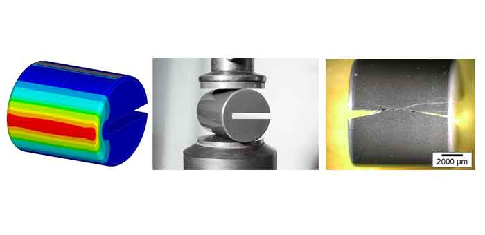
For roller testing, a similar long and narrow notch with a depth of about 80 % of the diameter of a cylindrical roller is cut symmet-rically along the mid-plane through the roller axis perpen-dicular to the end faces. In the strength test using such notched roller specimens, a load is applied at the line contacts of the notched roller diameter (fig. 9). Due to the more complex geometry, the underlying model is more extensive, but the practical execution is rather similar to the notched ball test [11,12].
Conclusion
Implementation of high-perform-ance ceramics in bearing applications requires a deep knowledge about material behaviour during processing and the finished product. Together, the presented tests allow a comprehensive and complementary characterization of actual rolling elements and enable identifying subtle differences in grindability, fracture resistance and strength depending on material microstructure, component size and rolling element surface finish.
, embedded ceramic sample (B) and acoustic sensor (C).")