Reliable motor control with newest generation SKF sensor bearings
The growing use of AC motors in a wide range of industrial applications increases the demand for accurate monitoring of speed and direction, even in challenging environments. SKF has introduced a new generation of sensor bearings that can meet tough operating conditions and deliver high performance at lower operating costs.
Summary
SKF is introducing a new generation of sensor bearings for AC motor control applications. These compact units offer reliable operation across a broad range of industrial applications from forklift trucks to golf buggies. Designed for increasingly tough operating environments, the new SKF Motor Encoder Unit, BMD, incorporates new features that offer enhanced sensor protection and easy integration into speed and direction control systems, resulting in improved resistance to electromagnetic fields, increased service life and reduced operating costs.
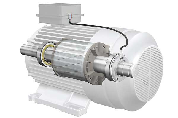
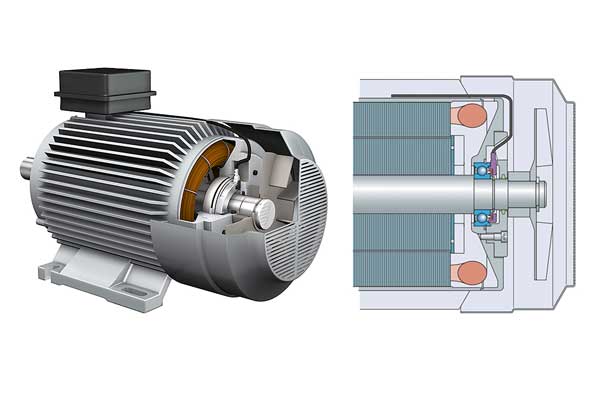
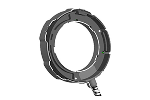
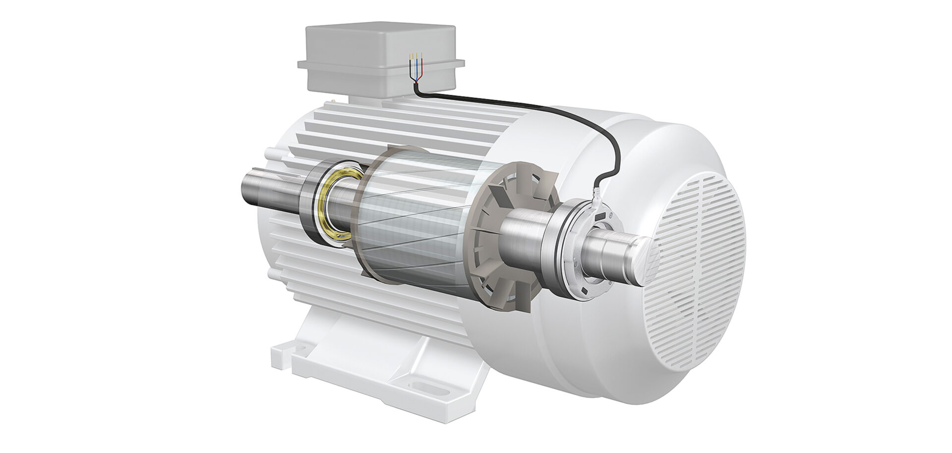
The latest development in sensor bearing design is the SKF Motor Encoder Unit, BMD (fig. 1). It has been developed to meet the requirements of a number of applications such as electric vehicles (fig. 2), forklift trucks (fig. 3), materials handling and agricultural (fig. 4), forestry and construction machinery. The new encoder unit meets the demands for reliable performance with a compact and robust design that offers greater resistance to magnetic and electromagnetic fields for improved up-time and reduced warranty costs.
As well as for these markets, there is growing demand for AC induction motors and associated control technology in the small electric vehicle sector, which ranges from personal transport to golf carts (fig. 5) and airport passenger vehicles, for example.
Increasingly, manufacturers of such equipment are striving to improve overall performance and reliability and to deliver cost-effectiveness through lower assembly and operating costs.
SKF Motor Encoder Units are used as feedback sensors in AC induction motors
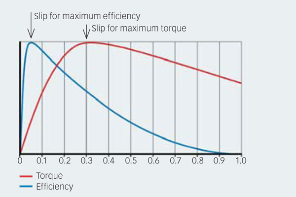
AC induction motors incorporate a frequency converter. The frequency converter creates alternating current with a variable frequency in the stator coils, which induce a current flow and magnetic field in the rotor. This induction needs a stator frequency higher than the rotor speed, the so-called slip. Induction motors cannot run at synchronous speed (stator field and rotor at same speed) as no rotor torque would be created. The maximum torque and motor efficiency is also a function of the slip (fig. 6).
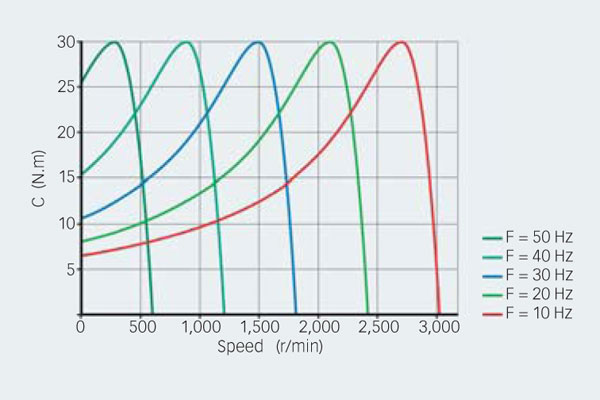
By varying the stator frequency and controlling the slip, i.e., the rotor speed with a feedback sensor, such as the SKF Motor Encoder Unit, the motor can run with maximum torque at different speeds (fig. 7).
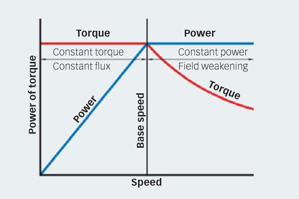
Traction motors in forklift trucks also run above the base speed. As a consequence, not to exceed the maximum power, the torque of the motor needs to be reduced (fig. 8).
History of innovation
SKF has a long history in sensor bearings, having introduced its first range of such products in 1995. Since then, SKF has made continual improvements, which have now resulted in the latest design, designated BMD, which represents the fifth generation of SKF sensor bearings for AC motor control applications (fig. 9).
Increasingly, SKF engineers are developing products that can be easily integrated into end-user designs while offering high reliability, reduced need for maintenance and lower operating costs. Like its predecessors, SKF Motor Encoder Units to the BMD design can be used with new and existing AC motor applications. The new BMD series has been developed to address two specific market requirements – to enhance protection for the sensor and to offer higher automation production at lower cost.
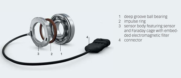
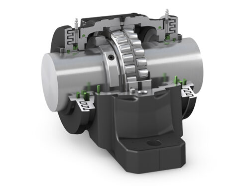
Increased robustness in both mechanical and electromagnetic environments, then, is at the heart of the design parameters. The BMD series incorporates 6206 SKF Explorer deep groove ball bearings that are defined by their small size, high performance and long life, equipped with a robust sensing technology (fig. 10).
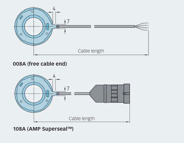
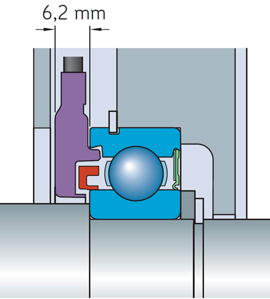
The encoder unit is available in two standard executions, either with or without an external connector (fig. 11). One of the benefits of the new design is that it can be used as a direct replacement for SKF’s previous sensor bearing designs, the BMB and BMO, without modification. As well as being fully interchangeable with these previous models, the BMD design supports automatic handling for ease of assembly and lower production costs. As the SKF Motor Encoder Units are compact, only a small amount of additional space, 6.2 mm, is required to accommodate the sensor technology (fig. 12). This is particularly useful for forklift truck applications, for example, where space is limited.
Sensing technology
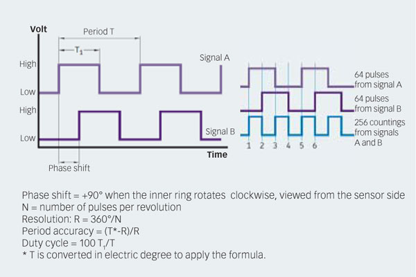
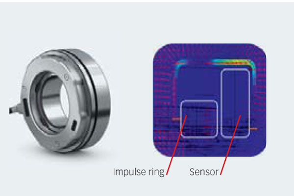
SKF Motor Encoder Units use Hall effect technology to produce an incremental encoder signal. Sensors based on the Hall effect are essentially transducers that vary their voltage output in the presence of a magnetic field. An impulse ring, which attaches to the inner ring of the bearing, is a composite magnetized ring that contains a number of north and south poles. The number of poles depends on the size of the bearing. The sensor body, which is attached to the outer ring, protects the SKF Hall effect cell. The sensor is accurate down to zero r/min. The sensor body contains both the control electronics and the Hall effect cell that produces an output signal consisting of two square waves (fig. 13).
The signals can be interpreted by motor controllers as required. For example, the direction of rotation can be determined from the phase shift, when the rising edge of a signal first appears. Slow speeds can be obtained by measuring the time between two electrical events, events being the rising and falling edge on either square wave. High speeds are measured by counting the number of electrical events within a given time period.
The two square waves are 90 ° out of phase with each other. This phase shift changes sign with the direction of rotation. The presence of two signals in quadrature enables a processing unit to multiply the number of angular position increments per revolution. For example, using a standard SKF sensor bearing with 64 pulses per revolution and a standard electronic interface that can detect the rising (Low/High) and falling (High/Low) times of each of the two signals, it is possible to obtain 256 electrical events per revolution, which translates to an angular resolution of 1.4 °
(fig. 13).
The attributes of this sensing system is that it works well over all speed ranges from extremely low speeds to about 12,000 r/min for units with a shield and 7,500 r/min for units with a seal. Another feature of the SKF Motor Encoder Unit, BMD, is its ability to work at ambient temperatures up to 150 °C. Such thermal performance is important in environments that are experienced in vehicle applications that produce thermal shocks, heavy vibration and extreme electro-magnetic conditions.
Protection features
The main risks for sensor bearings are voltage peaks, which lead to electronic overstress for the sensor electronics. Many different root causes can lead to voltage peaks , e.g., when the power wires of the motor are next to the sensor wires.
This design, protected by five patents, is also supported by new protective technology, one mechanical and one electronic, that further improves the robustness of the system. This is particularly important to protect sensor bearings against voltage peaks, which may cause problems for the sensor electronics. The mechanical protection for the sensor bearing is achieved by a Faraday cage that is formed by the outside of the sensor body, which provides an efficient physical shield against external magnetic fields (fig. 14).
The electronic shield is achieved through an integrated Electromagnetic Interference (EMI) filter to protect the sensor against power surges and electrostatic discharges. This filter improves electromagnetic compatibility protection alongside immunity to electrostatic discharges (ESD) and electrical fast transits (EFT) and radiation. The location of the filter is responsible for the high level of protection. Additionally, the filter is implemented on both input and output lines and does not have any influence on the signal itself. The performance has been tested to meet and exceed a range of EMC and ESD standards, required by many different industrial users. For example SKF tests the EMI filter at 25 °C and 125 °C, with 8 kV on signal lines, and the filter still functions at 22 kV (25 °C) and 15 kV (125 °C). They have been tested to meet the performance standards required by the industrial environment and the construction and agricultural machinery industries.
These features make the new SKF Motor Encoder Unit extremely reliable across all potential applications and minimize the risk of field returns and expensive repairs (figs. 14 and 15).