Factors in motorised spindle design
‘Utility supply units’ optimize motorized spindle performance.With motorised spindles – contrary to conventional spindles – a three–phase a.c. motor and spindle are combined to form a single unit. Optimised use of the spindle performance in conjunction with low manufacturing runs also demands optimum matching of the peripheral utility supply units, such as frequency converters as well as control, hydraulics, lubrication and cooling equipment.
The increasing use of motorised spindles in machine tools coupled with their process reliability has encouraged machine tool manufacturers and other machine producers to consider the potential of such spindles. While machine tool manufacturers are familiar with the problems of control systems, frequency converters, and cooling and lubrication units, this was novel ground for most of the other manufacturers.
This has induced spindle manufacturers to design and market complete ‘utility supply units.’
Well–supplied
Peripheral units for motorised spindles require precise matching.
The performance of motor elements for spindles largely depends on the selection of suitable frequency converters and cooling units, with the latter also affecting the thermal response of the complete motor spindle package. Further, operation of a motorised spindle usually requires a lubrication unit (oil/air lubrication facility) for supply of bearing lubrication.
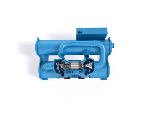
The utility supply unit is made up of additional components such as the control system, vibration control and bearing monitoring equipment, and an hydraulic system for actuation of the tool clamping devices together with a switch cabinet and, possibly, an operator panel. Fig. 1 shows a motorised lathe spindle.
Electric power supply to the motor is ensured by a frequency converter whose task usually consists of converting the comparatively low mains frequency (50 to 60 cps) into a higher frequency which is dependent on the motor speed and the number of poles. To ensure proper operation of the motorised spindle, the frequency converter and motor must be perfectly matched with regard to operating characteristics and losses. Another criterion to be considered is whether the speed is to be controlled in closed or open loop.
With closed–loop speed control, the converter defines the frequency as a function of the desired speed, and the actual speed which is measured on the shaft and returned to the frequency converter, thus enabling the converter to counteract a load–dependent speed drop by increasing the power output.
With open–loop control only the frequency is defined, permitting at least a considerably higher load–dependent speed decrease than with the closed–loop speed control system. As the decision on which type of converter should be used depends on the respective application, leading manufacturers of frequency converters have worked out suitable system solutions.
Cooling the stator
The stator is cooled with liquid media, which, as a rule, is oil or water with a corrosion protection additive. Since cooling is a co–decisive factor for the motor efficiency, cooling plants must be adapted to application–related requirements. A large switching hysteresis, for example, causes wide temperature fluctuations of the coolant in the spindle cooling area. These fluctuations correspondingly cause large thermal displacements of the overall spindle assembly (for example, axial mismatch due to thermally conditioned changes in the overall height) as well as of the shaft (such as thermally conditioned shaft expansion). In the most unfavourable instance, these may even result in a bearing failure. With a small switching hysteresis, on the other hand, the heat flow within the machine is minimised. This, again, causes only low thermal displacements in the entire machine. The plant units in question have a closed cooling circuit, avoiding unnecessary losses.
For lubricant supply to the bearings, an oil/air lubrication facility is required. In the plant unit manifold, a well–proportioned quantity of oil is admitted into a pipe pressurised with filtered compressed air. The air flow blows the oil along the piping wall towards the bearing point where, accelerated by air, individual oil drops are injected through a nozzle into each bearing. The parameters relating to proper functioning of the facility used for this purpose are monitored. Each spindle is tested in conjunction with the respective lubrication facility, and the required optimum lubricant quantity is adjusted during this test.
The tool clamping hydraulics is another component of the utility supply unit which is required on spindles with an integrated tool clamping system. An adequately rated hydraulic unit permits rapid clamping and releasing of the tool during tool changes.
Fast clamping
The hydraulic unit provides the tool clamping facility in the spindle with the required release pressure. For tool changing the spindle shaft is always located in the same position. In the case of closed–loop controlled systems and use of a suitable frequency converter, the shaft is held in position at the full motor torque. With other converters this requires greater input. On high–speed machines in particular, proper balancing of the tools is of major importance. Inferior balancing not only affects the spindle bearing arrangement but also causes a drastic decrease in the service life of the tools. In this connection, an aspect not to be under–estimated is that the tools must be balanced at service speed because in practical operation the imbalance position varies depending on the speed. However, for this application cost–favourable balancing equipment is hardly available, this not being surprising since the drive unit for the tool would again have to be a motor spindle.
A bearing monitoring system and a programmable logic controller offer a solution to this problem. After the measuring run, the spindle always stops with the point of the largest imbalance in a certain pre–defined position, so that the imbalance can be reduced by changing the mass distribution on the tool. In this way, a spindle–integrated sensor together with the bearing monitoring system not only serves for spindle monitoring, where the vibration velocity is taken as a measure for the running quality of the spindle, but also for tool balancing.
Advantages resulting from the compact design, reduction of the manufacturing penetration, short mounting and start–up periods, and years of experience with motorised spindles have led to the market being offered complete utility supply units. Fig. 3, for example, shows such a utility supply unit for an output of 50 kW.
Furthermore, utilising motorised spindles in conjunction with suitable utility supply units, avoids interface problems. The connections between motorised spindle and utility supply unit are all of plug–in type and equipped with quick couplers. A utility supply unit of this kind includes all the sub–assemblies required for operation of a motorised spindle, such as frequency converter, oil/air lubrication facility, re–cooling unit, and oil hydraulics for tool clamping operations.
The individual sub–assemblies are adapted to the respective spindle performance, and are optimised accordingly. Both the spindle and the individual sub–assemblies are controlled and monitored by a programmable logic controller. Service speed, bearing temperatures, operating condition of the plant unit and fault messages in clear text are indicated by an information panel on the utility supply unit itself or, alternatively, on the control desk (fig. 2). Instead of the information panel, a machine control unit may be used which communicates directly with the programmable logic controller.
Arnold Bokel,
SKF GmbH,
Schweinfurt, Germany