Robust bearing sets for low loads
Angular contact ball bearings usually have a contact angle of 40°. SKF has now extended its range of angular contact ball bearings with a new series of 25° bearings. For the first time, this makes it possible to produce asymmetrical bearing sets in a simple way that offers great service life advantages in axially loaded applications, such as pumps or electric motors – by solving well-known minimum load problems in a highly effective manner.


More options with a smaller contact angle and better cage
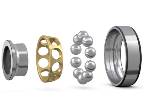
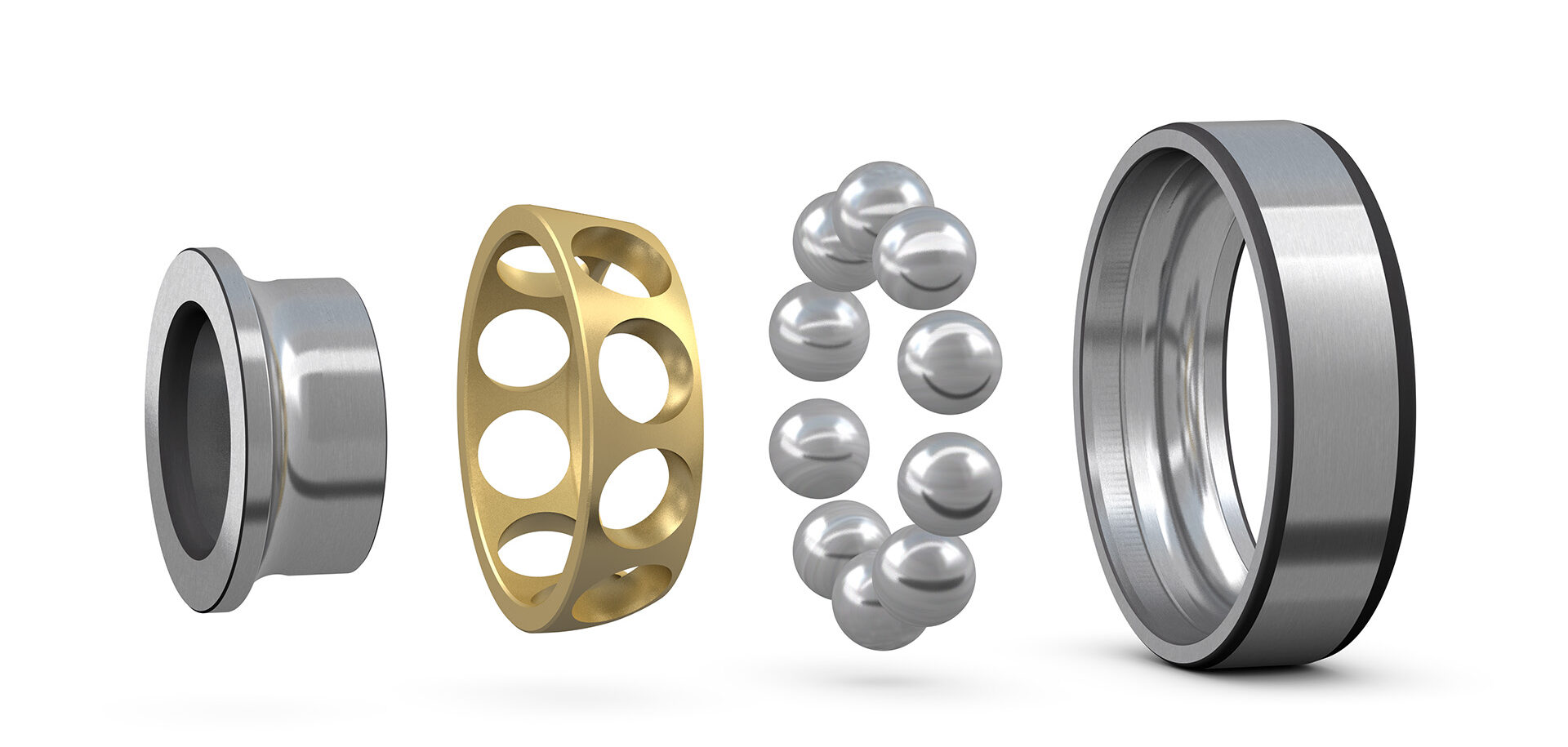
SKF has recently launched an extended range of single row angular contact ball bearings with a brass cage, which has a smaller contact angle than the usual 40°. Below is an overview of the new range of 25° angular contact ball bearings (suffix AC):


Applications and arrangements
The most common applications for angular contact ball bearings are pumps, compressors and electric motors. Such units, equipped with the improved SKF angular contact ball bearings, can run much more smoothly and achieve a longer service life.

As axial forces from both directions occur in most applications, the opposing forces must be absorbed by a counter bearing. The simplest form of a paired bearing is the double row angular contact ball bearing in a fixed “O arrangement” (following the shape sketched by the contact angle lines). Single, universal angular contact ball bearings can also be combined in different ways – in both O and X arrangements.

Paired angular contact ball bearings
When angular contact ball bearings are installed in pairs, various options are available for setting a defined preload or bearing clearance. The most common method is the use of so-called “universally pairable” bearings (also referred to as “universal bearings”). Universal bearings have the advantage that they are already matched to each other at the factory in such a way that a defined preload / clearance is achieved when they are mounted on blocks. The initial block gap between the inner or outer rings of the bearings is closed by clamping the bearings.


In order to reduce assembly costs, the new AC angular contact ball bearings with a 25° contact angle are already available in universal pair universally matchable versions according to the SKF Explorer class. Different preload and bearing clearance classes can also be realised on request.
Mixed bearing sets
Often the axial force of angular contact ball bearing sets is dominant from one direction. This can be the case, for example, with fans or pumps that mainly rotate in one direction. In such applications, an angular contact ball bearing absorbs the axial force, while the second angular contact ball bearing, the so-called “backup bearing”, is unloaded.


Advantages of mixed bearing sets
Previously, bearing sets consisting of two identical 40° single bearings have often been installed in such applications with a dominant axial load on one side. However, this is not an optimal arrangement, as the large 40° angle is more susceptible to minimum load problems when unloaded.
The new series with a 25° contact angle now allows the production of asymmetrical sets of 40° and 25° bearings. This bearing pair offers major advantages. In the asymmetrical bearing set, the dominant axial force is absorbed via the large contact angle (B = 40°), while the unloaded bearing with a smaller contact angle (AC = 25°) reduces the risk of smearing – because it increases the threshold for the lifting force. The lifting force is the external axial force at which a backup bearing in a preloaded bearing set is completely unloaded and the required minimum load is no longer guaranteed.
In concrete terms, this means that with the smaller contact angle of 25°, the backup bearing is unloaded less when subjected to the same external load. This dramatically reduces the risk of premature bearing failure, which in turn increases operational reliability.
Deflection and force distribution in asymmetrical, preloaded bearing sets
The advantages of an asymmetrical bearing set with regard to internal load distribution can be illustrated using the example of a preloaded bearing set consisting of two angular contact ball bearings in an O arrangement, which is subjected to a pure axial force F (red arrow). Bearing B with a 40° contact angle (suffix B) absorbs the axial force, while bearing A with a 25° contact angle (suffix AC) is unloaded by the axial force.

At the intersection between the blue and green lines (exactly on the y-axis), no external force is applied. Both bearings are only loaded with the set preload. In this example, a preload force Fpreload = 1 is assumed for simplification.
Positions 2 and 3 in general: Load ratios when an external axial force is applied in addition to the preload
When an external axial force F is applied in addition to the preload, you have to move from the intersection in the middle to the right in this diagram. Force F loads the 40° bearing (blue) in addition to the set preload force, so the blue curve rises. At the same time, force F unloads the 25° bearing (green), so the green curve falls.
As soon as the green curve hits the x-axis, the preload is used up and the bearing is unloaded. This must be avoided at all costs.
The dashed grey curve is used to compare with a 40° backup bearing. It shows the deflection in the case of a conventional bearing set with identical contact angles (40°+40°).
Position 2 in detail: force F1(40°) and force F1(25°)
Here, the difference between a conventional set (40°+40°) and an asymmetrical set (40°+25°) becomes particularly clear. The external force is exactly the same in both cases (F1(40°) = F1(25°) = 2.8 x Fpreload). However, the bearing sets deflect differently.
Force F1(40°) is represented by a dashed line, force F1(25°) by a solid line. With a conventional set of two 40° bearings, the point of lifting force would already be reached at this point. This can be seen from the dashed grey curve showing the deflection of a 40° backup bearing that intersects the x-axis. Here the preload is completely used up (intersection of the dashed lines, yellow box). This point is about 2.8 times the preload force.
With the asymmetrical set, however, there is still a certain residual preload in the bearing when the same force is applied. In this case, the green curve is still above the x-axis (intersection of solid lines, yellow box).
Position 3 in detail: force F2
The point of the lifting force for the 25° backup bearing is shown here. It is noticeable that the force F2 is significantly greater than the force F1. In concrete terms, this point is about 5.2 times the preload force. This means that the asymmetrical bearing set can absorb almost double the axial forces – compared with a homogeneous bearing set – without unloading the backup bearing.
The 25° bearing is therefore much more suitable as a backup bearing.
Conclusion
The new generation of SKF angular contact ball bearings with a 25° angle represents an ideal backup bearing solution. Especially in applications with a dominant axial force from one direction, the recommendation is to include an asymmetrical bearing set in the design to prevent problems with the minimum load not being achieved and to avoid premature bearing failures.
In addition, the bearings with a 25° contact angle can also be used in applications where high speeds and/or increased radial stiffness are required.
Keep in mind
When used correctly, the bearing set can also be designed with a lower preload or higher axial bearing clearance when using bearings with a 25° contact angle, resulting in lower internal contact pressures and therefore longer bearing life and less friction.
The expansion of the SKF angular contact ball bearing range with the 25° contact angle opens up new possibilities for the designers to provide optimal support for a wide variety of applications. SKF’s technical consulting service can also offer advice on selecting the most suitable bearings for individual projects.