Advanced numerical simulations for optimized seal designs
These days, numerical simulations are key in developing new products and improving existing ones. To improve the overall product design and the support to customers, SKF is equipping product engineers with Finite Element tools, developed at the SKF Engineering & Research Centre in the Netherlands
Summary
Numerical simulations are playing an important role in different stages of the life cycle of an increasing number of products. Virtual simulations reduce costs throughout the concept development and prototype phases as a result of extensive numerical analyses, enabling improved prototype designs to be physically tested.
There are several commercial calculation tools in the market that have proved to be very reliable and widely applicable in different fields. These software packages are designed for general use and thus are able to investigate several types of phenomena. However, highly skilled users are necessary to run such tools as well as to interpret the results and to convert them into meaningful solutions.
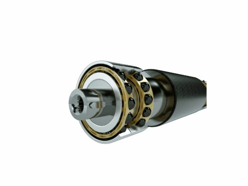
SKF has a long experience in numerical simulations, not only in the use of these commercial simulation packages but also in the development of in-house calculation tools. The Orpheus and BEAST platforms are used daily by SKF engineers to provide answers and to support customers. With these in-house tools, bearing applications have been simulated by SKF in multiple ways and complexity levels. This experience and these tools are continuously being enhanced with new functionality and capability to meet the SKF vision for numerical simulations where all components – bearings, shafts, seals, gears and housings – are simulated as a complete system (fig. 1).
Seals and numerical simulations
The first step towards the simulation of complete systems is the simulation of seals as single components (fig. 2). This initial detailed focus on a single component involves SKF gaining an even more in-depth understanding of the performance of the seal once it is installed in its final position.
Numerical simulations of seals involve several mechanical aspects. In the following, these aspects are briefly described to provide an overview of the complexity of seal simulations as well as the technology SKF is developing in order to provide product engineers with powerful and reliable software.
Simulations of rubber: a highly non-linear material
Many of the engineering calculations done today are based on the assumption that the material behaves linearly and elastically – that is, that force and displacements are linearly dependent on a constant, which is called stiffness. Rubber materials in general behave non-linearly. It is not enough to define one constant to relate force to displacements or stress to strain. Instead, rubber requires more complex constitutive models that can handle multi-axial non-linearity.
Amongst others, hyperelastic models are often used to simulate rubber behaviour. These material models are elastic, but as shown in fig. 3, outside a certain stretch range the non-linearity of the stress-strain relation deviates significantly from linear behaviour. Moreover, the material response depends highly on the orientation of the deformation.
Rubber is the most common seal material, because it enables the seals to follow the movements of the counter surfaces they are in contact with, such as shafts, rods or bearings. For the simulation of seals, it is therefore necessary to have a reliable way of simulating hyperelastic material models that can undergo large deformations in multiple orientations.
Simulations of rubber: an almost incompressible material
Rubber is also a nearly incompressible material – that is, the variation in volume of a compressed or stretched sample of rubber before and after the deformation is almost zero. This is a peculiar material behaviour, which challenges the numerical methods implemented in traditional simulation software. The incompressibility of rubber produces numerical instabilities normally indicated as “volumetric locking”. To cope with such a challenge, a special implementation of the integration scheme has been implemented in order to provide correct and stable results [1].
A literature search has pointed towards the solution of the volumetric locking being the F-bar method [1], which requires a modification to the traditional integration methods presented in literature [2]. On this aspect, collaboration with the academic world, in particular with Twente University in the Netherlands, has demonstrated the accuracy and the precision of the implemented algorithms. This has allowed the quality of the calculation to be comparable to the load calculation predicted by one of the commercial FE packages, such as ABAQUS, Marc or ANSYS.
Simulation of seals: contact mechanics to deal with interference
Sealing elements need to be installed in the working position with a certain given interference between the bore and the shaft. Therefore, it is crucial to be able to simulate the contact between the seals and the surrounding surfaces (such as housings, shafts, flingers or bearings) (figs. 4 and 5).
To correctly simulate the interference between seals and the surrounding parts of the application, contact mechanics have been one of the key requirements included in the development of the software tool. Contact can be solved in numerical codes in different ways. Considering the nature of the material that is normally in contact (usually rubber against steel), it is assumed that there is no co-penetration between the bodies in contact. This assumption has led to the adoption of the Lagrange multiplier method (the seal deformation is forced to mathematically equal the constraints, given by the surrounding counter surfaces) instead of the penalty method (the seal deformation is forced by means of penalty functions, which are activated as soon as the constraints are violated).
Simulations of a sealing system: FE solver
The best way to combine all the above items in numerical simulations is to use the power of the finite element method (FEM). In fact, this method can easily handle the combined aspects of hyperelastic material models, large deformations, contact mechanics by means of the Lagrange multiplier method and special implementation to avoid the numerical locking problem due to material incompressibility.
SKF Seal Designer
SKF, with the support of the SKF Engineering & Research Centre, has equipped its product engineers with a state-of-the-art calculation tool based on the Orpheus platform. The released tool is called the SKF Seal Designer.
The major capabilities of the software are covering both manufacturing (shrinkage from the mould tooling to finished geometry) and performance (installation on a shaft and/or inside housing) predictions.
Manufacturing simulation capabilities are available to SKF’s product engineers so as to improve the study of the design on the final shape of the seal. It is also used to improve the mould geometry, which is one of the most important parts of the overall design process due to its cost contribution, but also because mould geometry can be reused for other designs.
The capability of calculating the seal installed on a shaft is an additional feature. When a seal is installed, it exerts a force on the counter surface called lip force (fig. 6). Lip force is one of the most important parameters of a seal for both static and dynamic operating conditions. Lip force ensures the desired sealability, but it is also responsible for the seal friction under the lip. In addition, a garter spring could be used to keep the sufficient lip force for sealing as the seal material is ageing (fig. 7). For this reason, an accurate prediction of the lip force under different operating conditions is a crucial requirement for a simulation tool that will help to reduce the number of design iterations, and therefore time-to-market for new products (figs. 8 and 9).
Conclusions
SKF Seal Designer has brought the power of FE simulations to SKF’s product engineers. The tool provides reduced time-to-market by enabling product engineers to assess virtually how seal parameters, customer design requirements and application requirements affect seal performance.