Bearing insulation prevents electrical current damage
Insulated bearings prevent premature bearing failures eventually caused by stray electrical currents. Insulation properties must remain stable regardless of environmental conditions, in particular when bearings are stored, handled and operated in humid climates.
Why insulating bearings?
Bearing damage can occur when electrical currents use the rolling contact as a conducting path.
Today, a number of publications are available that deal with this matter, including discussions about root cause and counteractions, for example [1, 2, 3, 4].
The tribological regime of a bearing determines the electrical behaviour of the rolling contact and the possible outcome.
In the conductive state the bearing is at a standstill and shows a low ohmic resistance. Due to the relatively good metal-to-metal electrical contact, only very high amperage currents such as welding currents are able to destroy the raceway surface.
The resistive state is present if the bearing is in a mixed lubrication regime with increased ohmic resistance. In this regime, low electrical currents in the range of a few amperes have the potential to be dangerous.
In the capacitive state the bearing is in a full film lubrication regime, and it acts like an electric capacitor with a specific breakdown voltage. If the applied electric field strength present in the lubrication film of the contact zone is high enough (in excess of the threshold value) electric discharges, called EDM (electric discharge machining) currents, will occur.

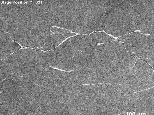
All damage cases have one thing in common: the contact area of the raceway becomes molten locally and the material properties of the steel in that area are changed. Additionally, the properties of the lubricant might be altered. This has a negative effect on the bearing performance in the form of raceway and lubrication damage and consequently results in increasing wear and bearing vibration levels. The effect of EDM currents, visible as microcraters, is shown in figs. 1 and 2. Microcraters are a consequence of high-frequency bearing currents. Today, this kind of damage is most commonly observed in applications using frequency convertors. One solution to counteract the possible destructive effects of damaging electrical currents is to use electrical insulation integrated into the bearing.

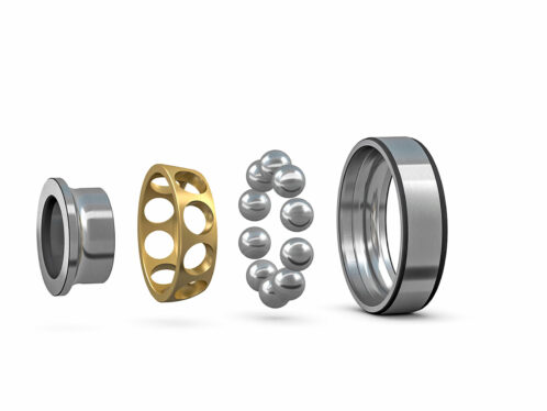
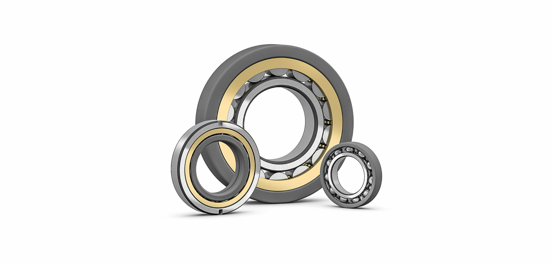
INSOCOAT – a bearing with an integrated thermal spray coating
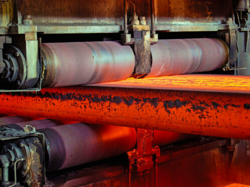
INSOCOAT bearings provided by SKF are bearings equipped with an electrically insulating coating applied to the outside surfaces of the bearing outer or inner ring to integrate the insulating function into the bearing. The coating material is of oxide ceramic nature (fig. 3) and applied on the bearing by using thermal spraying . Most commonly pure Al2O3 is used. Sometimes oxide mixtures are applied because of different desired electrical and mechanical properties of the resulting coatings [5, 6]. During spraying, oxide particles are transported through a hot plasma stream where they become molten. This hot gas or plasma stream transports most of the molten particles to the pre-treated substrate, where they cool down and form the desired coating.

Fig. 4 shows the microstructure of the resulting coating on a bearing outer ring.
After spraying, the coating shows a certain amount of open and interconnected pores, a common property of thermal spray coatings. The amount and appearance of porosity depend strongly on the coating process parameters. It is easy to understand that porosity closing, “sealing”, is crucial in thermal spray processing. This reduces the risk of corrosion, improves the mechanical properties and keeps the insulating properties constant, which is very important in humid climates.

Fig. 5 shows an example of closed porosity, a typical pore that is interconnected with smaller pores in a thermal spray coating. Many different sealing strategies have already been discussed in the literature [5, 6, 7]. For electrical insulating thermal spray coatings, the most practicable is a sealing step with organic sealants. Possible sealants have different properties in terms of viscosity, curing temperature, evaporation characteristics, shrinkage, etc. The entire process, thermal spraying and sealing, needs to be thoroughly evaluated to reach the desired coating properties.

Previous generation INSOCOAT – shortcomings and solution
In a number of applications in very hot, humid climates, low insulation resistance values of the previous INSOCOAT bearing generation were detected. The resistance of electrical insulators is always a combination of its surface and volume resistance [8]. In addition to fundamental material properties, both parts are a function of humidity and temperature. While the surface resistance part reacts immediately to a change in climate, the volume resistance part changes over a longer time period. If the insulating properties are out of the desired range, the whole insulating coating system has to be improved [5, 6, 7].

Experiments on previous generation INSOCOAT bearings verified the issues claimed in the field by analysing INSOCOAT’s electrical resistance in direct contact with water1. It turned out that the coating absorbs water on a long time scale and the effect was completely reversible after drying. Due to the long-time process of the resistance drop, surface currents, open porosity or cracks have been excluded as root cause. Therefore, the coating material, oxide and/or the sealant itself has to be the root cause. As a consequence, extensive research and testing activities have been started. It has been necessary to evaluate different coating and sealing strategies to find a solution. For example, different spray powder materials, sealants, curing processes and thermal spray strategies have been tested. A first evaluation was done as mentioned above, in direct contact with water. Although this test represents unrealistic conditions (in real applications the bearing or the motor is not immersed in water), it gives a very quick and sensitive feedback about possible success or failure. Some test results of good (V1 & V2) and negative examples (V3) are shown in fig. 6, always in comparison with the previous-generation INSOCOAT bearing variant. V2 was the best candidate for the new INSOCOAT generation.

New-generation INSOCOAT bearings
Fig. 7 shows the electrical performance of the new-generation INSOCOAT bearings in comparison with the previous variant under real conditions. This means that the bearings are mounted as they are in the field and exposed to varying climatic conditions in a climate chamber. The measuring set-up is shown in fig. 8. The test results show that the new INSOCOAT variant is much less sensitive to humidity than the previous bearing generation.
Conclusion – new INSOCOAT bearing generation
The new generation of INSOCOAT bearings has been optimized for high and stable electrical insulation resistance, even in very humid environments. Validation conditions were also chosen to simulate extreme climates. In addition to the data shown here, other parameters were checked and validated, such as low- and high-temperature performance (–40 °C up to +150 °C), mechanical performance (coating adhesion, mounting/dismounting stresses, impact resistance), high-voltage performance up to 6 kV DC and media compatibility.

Even at relative humidity levels greater than 90 %, at a temperature of 30 °C, the ohmic resistance of the tested 6316/C3VL0241 bearing stays above 2,000 MΩ, whereas the previous variant drops down just above 50 MΩ.
1 Water with a certain conductivity
INSOCOAT is a registered trademark of the SKF Group.