New bearings for high-speed applications
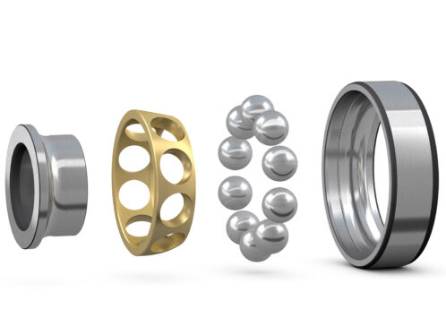
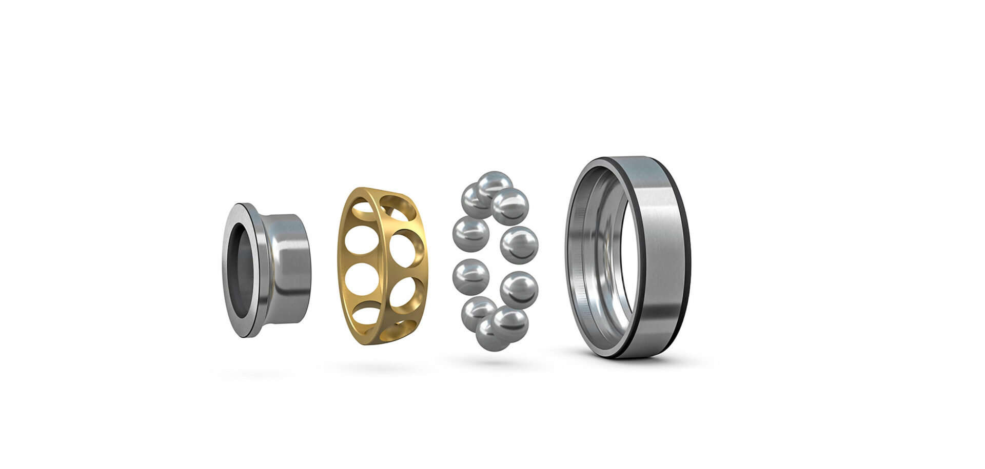
Single-row angular contact ball bearings are typically used in applications such as screw, scroll or centrifugal compressors (fig. 1) and pumps.
A clear trend in compressor and pump applications is to raise the power density by increasing the rotational speed. To fulfil this requirement, SKF has developed a new range of single-row angular contact ball bearings. The goals have been threefold: to increase the limiting speed by 40 %, to reduce the noise levels and to increase the robustness of the bearing in unfavourable operating conditions (shock loads, shaft misalignment, etc.). Apart from these, SKF is helping manufacturers to meet customer demands for even higher levels of energy efficiency and reliability.
Summary
Bearings in the new SKF Explorer single-row angular contact ball bearing assortment with 25° contact angle, equipped with a new brass cage and an improved raceway geometry, can withstand much higher speeds (up to n×dm = 1,050,000 mm/min) and are more robust in severe operating conditions compared to SKF Explorer single-row angular contact ball bearings with 40° contact angle.
The new 25° contact angle assortment from bore diameter 15 mm up to 70 mm in the 72 AC series and from 17 mm to 70 mm in the 73 AC series was launched in April 2017 and is available from stock or in a short time.
Because of the modular single-row angular contact ball bearing design, customers can choose the most suitable cage, sealing and contact angle to design new compressor generations that are more efficient and reliable, to reduce total costs of ownership for the operators.

Based on some concept studies, the following features were developed and implemented in the new SKF Explorer single-row angular contact ball bearing assortment:
- 25° contact angle
- new cage design, stronger brass material
- improved raceway geometry.
25° contact angle
Single-row angular contact ball bearings, as standard, have a 40° contact angle. In applications with high demands on axial stiffness, such as machine tool screw drives, angular contact ball bearings with larger contact angles (e.g., 62°) are often used. For bearings in high-speed applications with moderate axial loads a smaller contact angle (e.g., 15° or 25°) is preferred.
The influence of 40° and 25° contact angles on bearing properties is shown in table 1.

Bearing kinematic effects of different contact angles (fig. 2)
If a single-row angular contact ball bearing is loaded purely in axial direction, the resulting contact forces between balls and rings become higher with smaller contact angles. When the bearing rotates, centrifugal forces (Fc) cause contact angle changes. The contact points between the inner ring and balls, as well as between the outer ring and balls, will move outwards. This effect causes a contact angle variation (∆α) and subsequently sliding between balls and rings. When applying the same axial load on single-row angular contact ball bearings with different contact angles, the contact angle variation is much smaller for bearings with smaller contact angles. Fig. 3 shows the contact angle variation of type 7313 single-row bearings with 40° and 25° contact angle at different speeds.

Less contact angle variation not only results in less sliding between balls and rings, but also results in reduced cage pocket forces. This is the reason why bearings with a 25° contact angle can operate with higher speeds without cage fracture.

Optimized brass cage design
In high-speed applications the cage is a crucial bearing component. Therefore, for bearings with a 25° contact angle, a new brass cage has been developed. The following improvements were implemented in the new design:
- toroidal shape of the cage pockets (fig. 4)
- reduction of the cage pocket axis angle
- optimized cage pocket clearance
- oval cage pockets
- optimized shape of the outer outline
- new brass material with improved mechanical properties and less lead content.

The cage pocket geometry has been defined based on finite element analysis. All simulations were done with BEAST, a state-of-the-art SKF proprietary bearing simulation software. The contact forces between cage and balls were analysed for different operating conditions and with various pocket geometries (fig. 5).

Finite element analyses were carried out to compare different design variants. But for a comprehensive verification of new products, physical tests are essential. In addition to robustness and friction tests, a large number of high-speed tests were made to verify cage performance. Based on the positive test results, the limiting speed for the newly developed brass cage was increased by approximately 30 % (fig. 6).

Due to an optimized ball-to-cage contact (toroidal shape) the temperature behaviour at high speeds is more stable and the lubricant film formation was improved. Based on the oval cage pocket design, where the clearance in axial direction was reduced, the noise and vibration levels could be reduced by 15 %.
Cage costs
To successfully launch a new product, two factors are crucial: customer values and costs.
For this reason, cage costs in particular were observed during the whole development process of the new cage. Flexible manufacturing processes have made it possible to realize more complex geometries without additional machining costs. Furthermore, due to the possibility of using a reduced cross section of the raw material tube (fig. 7), machining time has been reduced.
.")
Due to the improved performance, this optimized brass cage design will also replace the existing cage design in the 40° contact angle assortment in the 72 B(E) and 73 B(E) series, the bearing designation will remain unchanged.
Improved raceway geometry
The raceway profile of ball bearings is usually a circular arc. In severe operating conditions with axial shock loads and shaft misalignment it can happen that the contact ellipse reaches the edge of the shoulder (truncation), which causes high stress peaks. These unfavourable loads can be a reason for early bearing damage and failure. To reduce this risk, the raceway geometry for bearings with 25° contact angle was improved, so that a second circular arc (r2) with larger osculation was added (fig. 8).

With the new raceway geometry, the risk of ellipse truncation has been reduced significantly. Singlerow angular contact ball bearings with the new raceway geometry can accommodate axial forces up to approximately three times higher without ellipse truncation, compared to bearings with a constant raceway radius. Due to this new raceway geometry the contact pressure is slightly higher because the contact area has been reduced. This contact pressure increase depends on the axial and radial loads acting on the bearing. For typical application conditions the contact pressure increases are always less than 1 %.
SKF Explorer is a registered trademark of the SKF Group.