How modelling and simulation helped build the world’s largest observation wheel
When you are building the largest observation wheel in the world, Las Vegas’ High Roller, you had better make sure that you use the best-engineered components and processes. When SKF teamed up with Arup, the observation wheel designer, and American Bridge, the construction contractor, to design the main spindle and hub arrangements, it applied the latest analysis and design tools to ensure that the wheel keeps turning day and night.
Summary
At a height of 168 m, the High Roller in Las Vegas is the biggest observation wheel in the world. Each of its 28 air-conditioned pods holds up to 40 passengers for a 30-minute ride that takes in the whole of this vibrant city. It is part of a 550 million US dollar open-air shopping, dining and entertainment district, the Linq, which has transformed the landscape and given visitors a new perspective on the Strip. The High Roller design was announced in August 2011 and opened in March 2014.
Behind the glitz and glamour of this new attraction to the Las Vegas skyline is the sheer engineering feat of building a giant engineering structure that has to meet stringent safety and tough operating conditions. SKF was asked to design, supply and assemble the spindle bearing system by the prime structural contractor, American Bridge, which installed the system and also worked closely with structural engineers for the project, Arup Engineers, which created the specification. Arup also worked on the previous largest wheel in the world, the Singapore Flyer.
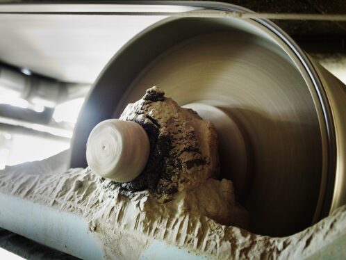
For the High Roller, the wheel rotates on a pair of SKF custom-designed spherical roller bearings, each weighing approximately 8.8 tonnes. Each bearing has an outside diameter of 2,300 mm, a bore of 1,600 mm, and a width of 630 mm. The double row spherical roller bearings have 30 rolling elements per row, and the bearings are the largest ever built by SKF at its Gothenburg factory. A simulation model was used to determine the optimal radial bearing clearance for this application. Specially engineered features include W26 lubrication holes in the inner ring, SKF NoWear-coated rollers, and PTFE coating in the bore. In addition, the system incorporates advanced automatic lubrication and sealing arrangements.
The structure is based on a 143 m diameter tension wheel. In addition to the two SKF bearing assemblies, the structure is made up of four steel support legs, a single braced leg, fixed spindle, rotating hub, 2 m diameter tubular rim, and 112 locked coil cable assemblies as spokes. The passenger cabins are mounted on the wheel’s outboard rim and are individually rotated by electric motors to maintain a horizontal cabin floor throughout each full rotation.
Design criteria
When considering the spindle bearing system (fig. 1), there were a number of challenges to be met, not least the need to deliver a safe and reliable solution. For the spindle and bearing, there are heavy loads and large housing deformations to be considered, with varying alignments for the spindle. According to the specification forces on the observation wheel, loads are 1,350 tonnes per end. For each of the 56 bottom radial cables, the tension of the cables is 132 tonnes and for the top 56 cables, is 47 tonnes, with the total radial cable tension being 4,600 tonnes.
For the design a rotational speed around the Z-axis of 0.033 r/min. was assumed. The model assumed a constant wind load to be applied to each bearing. This load is applied to the outside outer ring of each bearing in the Z-direction. Different wind loads were used in the various service case simulations. The calculated bearing misalignment includes the effects of the constant wind loads associated with different service conditions, though the effect of fluctuating wind loads was not included in the simulations.
Bearing loading during installation was another key factor to be considered. Bearing failure can be extremely expensive and disruptive, so from the outset SKF applied a Six Sigma approach to the project from design through to manufacturing and assembly. As a key component for such a prestigious attraction, it was important to ensure that the design criterion for long bearing life was met. To that end, SKF used extensive and sophisticated analysis tools, based on best-in-class engineering principles, to ensure that the bearing and spindle design lived up to stringent specification and performance requirements.
Approach to the project
The design and analysis part of the project was split into four phases and used extensive modelling and analysis software to ensure that the final design would live up to actual operating conditions. The aim was to evaluate the complex interaction of all the components in the system and to identify key performance indicators. In essence, the purpose of the project was to study system interaction, including the effect of housing deformations, contact load distribution and contact pressures on the bearing raceways. Particular attention was dedicated to the evaluation of the effects of loadings and deformations to the bearing performance in terms of forces and motion.
SKF has advanced simulation tools that have been developed specifically for the study of rolling bearing applications and to evaluate the many factors that influence the system behaviour, such as clearance in the assembly, misalignments, supporting structure flexibility and different boundary conditions.
The project phases were carried out as follows:
Phase 1 – Project definition using Design for Six Sigma
- project definition
- DfSS core documents
- design data collection.
Phase 2 – Bearing simulation analysis
- rigid bearing model with point loads
- deflections and deformations as inputs
- flexible model including hub and spindle components
- loading provided in the form of cable tension (four simulation cases).
Phase 3 – Bearing sensitivity analysis
- effects of changes in boundary conditions
- review of the bearing internal design
- parametric study of the bearing internal geometry
- FE analysis of the cage.
Phase 4 – FE analysis of the sleeve drive-up forces during installation
- FE model creation
- FE analysis of the drive-up forces without cable loads
- FE analysis of the drive-up forces with cable loads.
Phase 1 involved clearly defining the project and identifying all the information and documents required to follow a Design for Six Sigma (DfSS) approach. Part of the DfSS methodology is the use of Failure Mode and Effect Analysis (FMEA) to drive the development of engineering activities and solutions. FMEA was used to help the design team identify the potential causes of failure based on previous related experiences, and served as a reference in selecting design features, simulation activities and recommendations. The FMEA was developed by a team consisting of Arup, American Bridge and SKF.
In practice, the starting point to create the DfSS core documents included identifying the parameters that influence the fatigue life of the bearing (fig. 2) to produce a boundary diagram that defines the interactions of the bearing system with its surroundings, including the inputs and desired output. Another diagram, the P-diagram, is used to identify all the design parameters that control, and the noise factors that have adverse effects on, the desired output or outcome, i.e., performance.
SKF then moved into concept generation and selection in Phase 2. With a bearing configuration in mind, analysis of bearing performance was carried out using simulation models created above. This involved the application of the software package, SKF Simulator (Orpheus), which has been developed for the investigation of rolling bearing applications as a total integrated system. Orpheus is capable of analysing static and modal behaviour of the bearing application. First, a model is built by connecting all types of machine components, such as bearings, shafts, gears and housings. An arbitrary combination of forces, prescribed displacements and rotational velocities can be used to define the loads on the components. The components themselves may be special (non-linear) elements, defined within SKF Simulator (i.e., the rolling bearings), as well as arbitrary elements like shafts and housings. The latter must have a linear behaviour, and their stiffness and damping properties are obtained by means of the finite element method. Special reduction methods are applied (on the original finite element models) to reduce the number of degrees of freedom and thus to reduce the calculation time for analyses. For this project four different loading conditions were selected for analysis.
For the rigid (static) model simulations, the bearing was modelled as a single spherical roller bearing with four different sets of radial and axial loads applied to the outer ring. The inner ring was grounded in all degrees of freedom, while the outer ring was free to move in all degrees of freedom. A misalignment angle was applied as a relative misalignment between the inner and outer ring in both positive and negative directions (fig. 3).
Following this analysis, the modelling moved to looking at the effect of structural flexibility on bearing performance, and this involved adding the hub and spindle as fully flexible components to the model before performing further simulations based on the four case options.
One of the key aspects of the design project was to ensure that the bearing assembly would be able to live up to the real conditions expected in the real world. During Phase 3 the sensitivity of the bearing to changes in boundary conditions and internal geometry was performed. These analyses served to evaluate the bearing design under application conditions. SKF used further analysis to study this. One related to assessing the sensitivity of the bearing to changes in boundary conditions and the internal geometry. In addition an FE cage analysis was conducted. The bearing internal geometry analysis led to a revision of the roller profile initially used in this analysis.
Initial optimization runs identified the possibility of life improvements by varying the roller profile and the shaft/hub stiffness. The optimal design was selected, and then further simulations of the various loading conditions were evaluated.
Bearing life analysis
As previous stated, the bearings need to have a long and reliable life in the High Roller. To this end, SKF used two important bearing life calculation methods. The first was the DIN ISO 281. The second was the SKF Advanced Fatigue Calculation (AFC) life method.
The bearing calculated fatigue life values referenced are the L2.53 and the L10 raceway fatigue life. L10 bearing life is defined as 90 % of the bearings exceeding the calculated value with 10 % failure probability. Fatigue life with a lower failure probability can be calculated using a Weibull distribution with a shape factor equal to 1.5 and a form factor chosen appropriately. The L2.53 was chosen to increase reliability of the system.
All life calculations for this project were performed using the SKF advanced simulation program, SKF Simulator. For modern high-quality bearings the nominal or basic rating life can deviate significantly from the actual service life in a given application. Service life in a particular application depends on a variety of influencing factors including lubrication, the degree of contamination, misalignment, proper installation, environmental conditions, structural movements, vibrations while the bearing is stationary and electrical current discharges.
The SKF AFC life method takes the full integration of rolling element contact stress across the roller length into consideration, and evaluates the total number of stress cycles until life in the entire loaded volume is consumed. The SKF AFC life also incorporates the condition of the lubricant, taking into account operating film thickness and contamination for each contact individually.
SKF generated significant L2.53 increases due to the DfSS process and the resultant simulation analysis. Modifying the standard bearing roller profile, improving the stiffness of the hub, adding SKF’s NoWear low-friction, wear-resistant carbon coating to the rollers and specifying an automatic lubrication system increased the calculated life by over 10 %. The bearing was custom-designed for the application, in contrast to most bearings where the objective is to fulfil a variety of applications. SKF modified the roller profile to meet the low speed and heavy load application conditions.
Various simulations provided SKF with the data to recommend the best hub and shaft stiffness, considering technical and cost considerations. Rolling element contact pressures are directly related to stiffness of the hub and shaft. The cost of improving the hub and shaft stiffness was correlated to the expected improvement in L2.53 life. Based on these studies, the decision was made to improve the stiffness of the hub and shaft components. Life requirements were exceeded under all conditions.
Finally, the results of the simulations were utilized to determine the procedures and equipment that were required for the installation. The installation procedure simulations were nearly identical to actual field assembly. The installation, as predicted, required the use of hydraulic injection assist in mounting the bearings properly. The axial drive-up required to achieve the final mounted internal clearance was within 2 % of the calculated value. This was very impressive given the complexity of the hub design.
Conclusion
The Six Sigma approach to the project, along with the simulation tools, provided SKF with the process and tools to design a hub assembly solution that met the technical requirements of the project while considering manufacturing, transportation, construction and financial constraints. The spindle assembly solution provided by SKF was delivered on time and within budget.
NoWear is a registered trademark of the SKF Group.