New challenges for rotor bearings in the 8-MW offshore category
With the “Round 3”, a 33-gigawatt offshore project in the UK, a new generation of offshore turbines has now been introduced.
Summary
The turbines in a new 33-gigawatt offshore project in the UK have extremely long rotor blades, up to 90 m, as well as a hub and blade weight of approximately 220 tonnes. The overhang from hub to tower centre is relatively large to provide adequate space for the bending blade tips. An objective is to develop drivetrains that are as light and as compact as possible in order to reduce the total cost of the machinery and the installation.
SKF offers a wide range of rotor bearings for differing drivetrain concepts in order to provide the best possible performance, in keeping with the turbine layout, and the lowest possible operating cost.
Spherical roller bearings in geared turbines
Two-point suspensions with a toroidal roller bearing (CARB) and a spherical roller bearing in separate rotor bearing housings have become established in the 5-MW category (fig. 1). The CARB bearing acts purely as a non-locating bearing; the axial movement function is realized by means of the flangeless bearing rings. The smaller spherical roller bearing, which is the locating bearing, is positioned at the generator side at a suitable distance from the CARB bearing. The inherent clearance in bearings of this size requires in future a more holistic, dynamic approach of the entire drivetrain and is, for example, relevant for the planetary carrier bearings of the gearbox as well as its gearbox mounts.

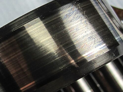
The self-aligning bearings help counteract pronounced shaft deflection, angle errors and offsets of both bearing housings very effectively. With the self-regulatory character they always independently adopt a position in which the load is equally distributed over the length of the rollers (fig. 2). Even when skewing or axial displacement takes place, the bearing load-carrying capacity remains very high.
The CARB bearing and spherical roller bearing two-point suspension is, due to its strong track record, predestined to be used in a new 8-MW modular-designed geared turbine. Based on a hollow shaft, a CARB bearing with a 1,700 to 1,800 mm bore and a spherical roller bearing with a 1,200 to 1,300 mm bore can be used. SKF also offers the “next generation” of CARB bearings and spherical roller bearings for these sizes. These bearings have considerably improved perform-ance parameters with regard to durability, operational capabilities and dynamic load-carrying cap-acity. The improved performance is provided by very high steel quality for higher fatigue strength, optimized X-Bite heat treatment and equal load distribution within the bearing.
SKF is challenged also to offer individually engineered housings for these bearing sizes. They are designed for optimal load distribution by taking into account the operating loads and deformation of the housings (fig. 3). Furthermore, SKF contact seals or labyrinth seals can be integrated depending on whether grease or (upcoming) oil lubrication is used.


Rigid bearings used in geared turbines
The design comprises a cylindrical roller bearing and a double row tapered roller bearing (fig. 4). This arrangement has been proven for years in gearless turbines. This design provides interesting possibilities for main bearing arrangements – even for 8-MW geared turbines with a modular drivetrain design.
The manufacturing precision, form and position tolerances of both bearing outer ring seats are extremely demanding compared with the self-aligning bearing arrangement design. The arrangement requires a long joint rotor bearing housing in which both bearing outer ring seatings are produced in one set-up, thus eliminating radial misalignment (fig. 5).
With the assistance from SKF SimPro Expert calculation software, examination of the deformation of the rotor shaft as well as the bearing housings can be made, including the supporting structure for detrimental factors on the load area and the bearing misalignment.
According to experience, the design of the housing must be optimized and bearing raceways must be profiled so as to reduce edge stresses to a reasonable level. Generally, single row and double row cylindrical roller bearings with slim roller sets and optimally designed cages are needed for bearing bore diameters larger than 1,700 mm and are suited for an 8-MW turbine.
A double row tapered roller bearing is suitable in a face-to-face arrangement to act as a locating bearing on the generator side. For large bore diameters (> 1,000 mm) it is also necessary to constructively examine the use of bearing units in a TDI design (single-piece inner ring) as a possible alternative to two single row tapered roller bearings.
In comparison with the “flexible” CARB bearing and spherical roller bearing arrangements, “rigid” cylindrical and tapered roller bearing arrangements can be designed to be somewhat more compact (shorter).


A cross-located bearing arrangement with two single row tapered roller bearings in back-to-back position is also regarded as a “rigid” two-point suspension in geared and gearless turbines. Based on two individually designed single row tapered roller bearings with bore diameters approximately 2,200 mm, with different pressure angles and different load ratings, it is possible to realize a relatively compact rotor bearing unit in XXL format, based on a cast hollow rotor shaft and a one-piece housing for an 8-MW turbine (fig. 6).
Compactness and weight reduction are also key topics here. It is therefore necessary to examine the whole bearing arrangement for mounting options, stiffness, deformities and influences on the preload of both tapered roller bearings at an early stage of design. Due to the relatively small space between bearings in the back-to-back arrangement and the large bearing diameter, a loss of preload must be taken into consideration and the consequential influence on the bearing life. That’s a challenge, and a change to oil lubrication could be a suitable means within this arrangement to control the temperature level (thermal expansion) of the pre-loaded rotor bearing system.
SKF Nautilus bearing in geared turbines
Very compact drivetrains with a semi-integrated SKF Nautilus bearing in power classes from 2 to 6 MW with a rotor diameter of approximately 125 m have been realized in the past few years. In this case the structure of the mainframe encloses the moment bearing at the nacelle front side (fig. 7). All forces and bending moments are optimally transferred from the rotor shaft via the rotor bearing onto the turbine mainframe. The moment bearing is fixed on a short rotor shaft between the hub and the gearbox.


This double row tapered roller bearing in a back-to-back arrangement, along with the large bearing diameter, forms the basis for the large bearing pressure centre to accommodate and transfer the large tilting moments. The 45 ° internal contact angle and relatively small tapered roller angle meeting at the apex point provide pure rolling contact across the full roller length to the bearing raceways without roller sliding damage taking place. The design with SKF’s segmented cage provides the needed flexibility in order to cope with large system deflections under heavy loads.
In case of rotor diameters of up to 180 m in the upcoming 8-MW category, the overhang from the hub centre to the tower centre becomes even larger to provide adequate space for the bending blade tips. This means there is enough nacelle length available for accommodating a modular drivetrain with a two-bearing arrangement and a flange-mounted gearbox. When using an SKF Nautilus bearing, it is expedient to shorten the overhang of the hub to keep the connecting point of the blade hub to the moment bearing as short as possible and to enable the centre of gravity of the 80- to 110-tonne gearbox to act closely to the tower centre or beyond.
The same applies for 8-MW hybrid turbine concepts in which the entire drivetrain (rotor bearing, gearbox and generator) is integrated together as one unit. When integrating a rotor bearing within the gearbox, it is essential to de-couple the deformations in the rotor bearing and the surrounding structures from the following (planetary) gear stage. This makes sure that the driving gear input shaft has pure driving torque (up to 10,000 kNm nominal) and that the precise gear intermeshing is not disturbed.
SKF Nautilus bearing in direct drives
The selection of bearing types and their arrangement have an influence on the total deformation as well as the stiffness of the drive-train and therefore also the elec-trical generator design in terms of the magnet strength and mass and the generator air gap to be maintained. A reduction in the generator air gap size of just 1 mm can result in tremendous cost savings and an impressive rise in the efficiency of the turbine over the course of its working life.
In addition to the two tapered roller bearings, as well as the double-row tapered roller bearing and cylindrical roller rotor bearing concepts, primarily assembled on a stationary kingpin, the version featuring a moment bearing is increasingly used worldwide (fig. 8). The moment bearing acts as a central link between the hub and a slow-running generator, which is placed in front of the tower (“bug generator”).

SKF Nautilus moment bearing variants require detailed working out of bearing performance and optimization of the generator air gap (eccentricity, deflection, angular deflection), considering deformation of the whole design. In addition, there are also very pragmatic considerations relative to accessibility for changing seals as well as adding lubricating grease and removing old grease. For this purpose, SKF offers corresponding large seals in a single-part version and a split-type version.
To fulfil SKF criteria and external DNV-GL requirements for wind turbine certification, high bearing static and dynamic load ratings are required to further ensure the reference of 20 years of bearing performance.
The 8-MW class will need even higher bearing load ratings through the use of bigger rollers and ring cross sections. SKF is being asked to further develop bearing upgrades, inclusive new seals for oil lubrication and lubrication systems, taking physical limits into consideration.