SKF tribological black oxide coatings for improved energy efficiency of railway wheel-end bearings
With a growing global railway market that needs to reduce its energy consumption and CO2 emissions, railway wheel-end bearing units are being optimized to further reduce power losses without compromising reliability. One of the solutions being evaluated is the selection of an optimum surface engineering process. Results demonstrate that SKF Tribological Black Oxide can significatively reduce the bearing torque at both low and intermediate speeds, a fact that is particularly relevant to intercity trains.
Coated Rolling Bearings
There are many kinds of coatings that can be used on rolling bearings [2], but only a few can be used on bearing raceways [3]. There is a group of coatings known by the generic name “conversion coatings”, which are obtained by converting the bearing ferreous metallic surfaces into a coating by suitable electrolytic or non-electrolytic chemical reactions.
Phosphating Conversion Coatings: The coating is the result of a chemical reaction where the iron at the surface reacts with manganese, zinc or zinc-calcium cations and the phosphate anions in the fluid. For bearing applications, manganese phosphate or zinc-based phosphates have a thickness of 2–15 μm [2]. It is worth mentioning that phosphating implies acidic processes that might have a pitting effect if not properly done (thus increased risk of surface-initiated fatigue), which is not the case with the alkaline process of bearing oxidation (tribological black oxide) [4].
Oxidation Conversion Coatings: The coating is the result of a chemical reaction between the iron of the steel surface and the reagents. It produces a black layer approximately 1 μm thick comprising a blend of FeO, Fe2O3 and Fe3O4. Standard DIN 50938 [5] and the equivalent ISO 11408 [6] set a baseline for the method. However, it should be highlighted that both standards focus on anti-corrosion and are not optimized to obtain black oxide layers with tribological properties for rolling element bearing applications. SKF’s TBO coating is made following these standards but with optimized processes that enhance the tribological properties of the coating.
Coatings Morphology and Mechanical Properties
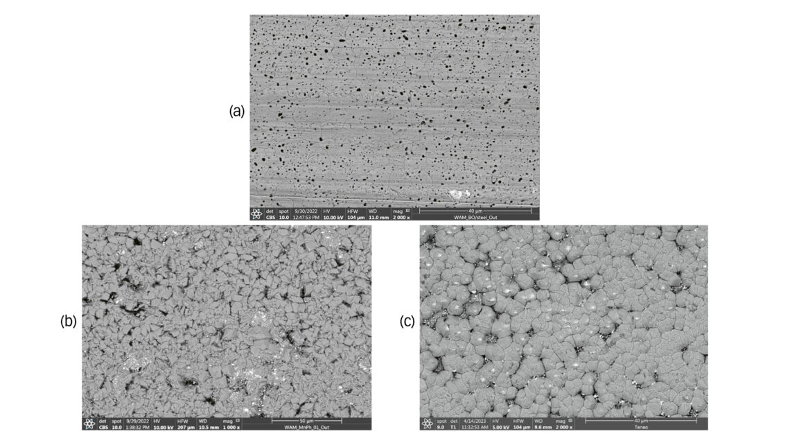
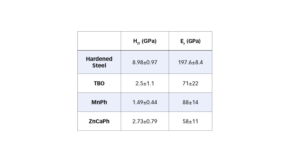
Fig. 1 displays scanning electron microscopy (SEM) plan-view morphology of the three conversion layers that were studied. The TBO coating (fig. 1a) shows the presence of voids and cracks. The void formation has been attributed to the nature of the oxide conversion, while the cracks have been linked to surface stress relief because the oxide layer has a different thermal expansion coefficient compared to the steel substrate. The MnPh coating (fig. 1b) exhibits a polycrystalline microstructure with prismatic-shaped crystals of 5–10 µm. The ZnCaPh coating has a compact microstructure with a uniform distribution of grains (fig. 1c), thanks to the incorporation of Ca during the phosphating process. Table 1 gives the mechanical properties of the coatings.
Reciprocating sliding tests
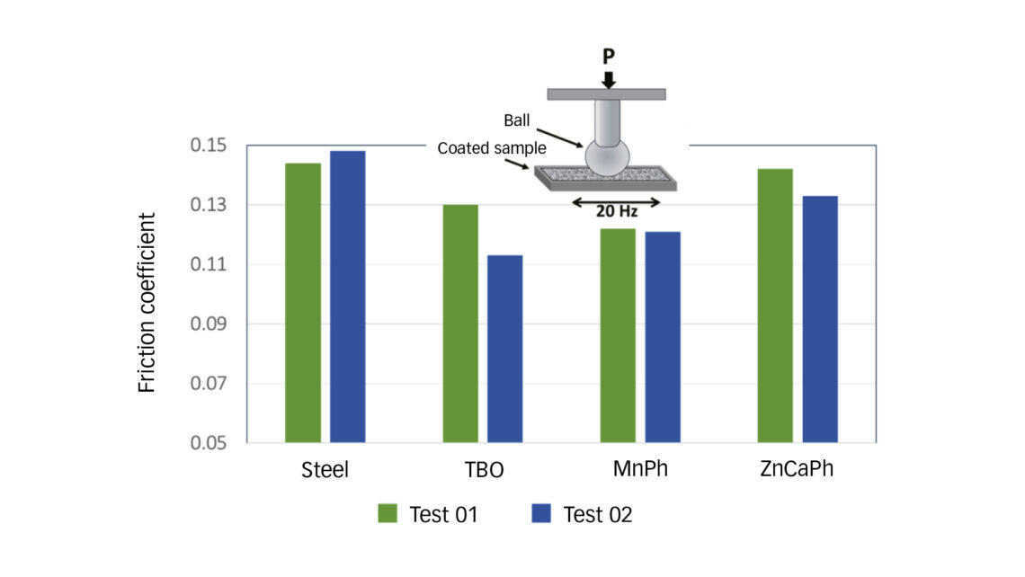
An inhouse fretting wear test rig (fig. 2) was used to measure the friction coefficient in pure sliding conditions. After a short run-in period, all coatings display a constant friction. Results indicate that, under such fretting wear conditions, the friction coefficient is lower for conversion coatings, likely due to the eased smoothening of the initial roughness peak. The lowest friction coefficient is obtained with the TBO-coated plates.
Rolling/sliding tests
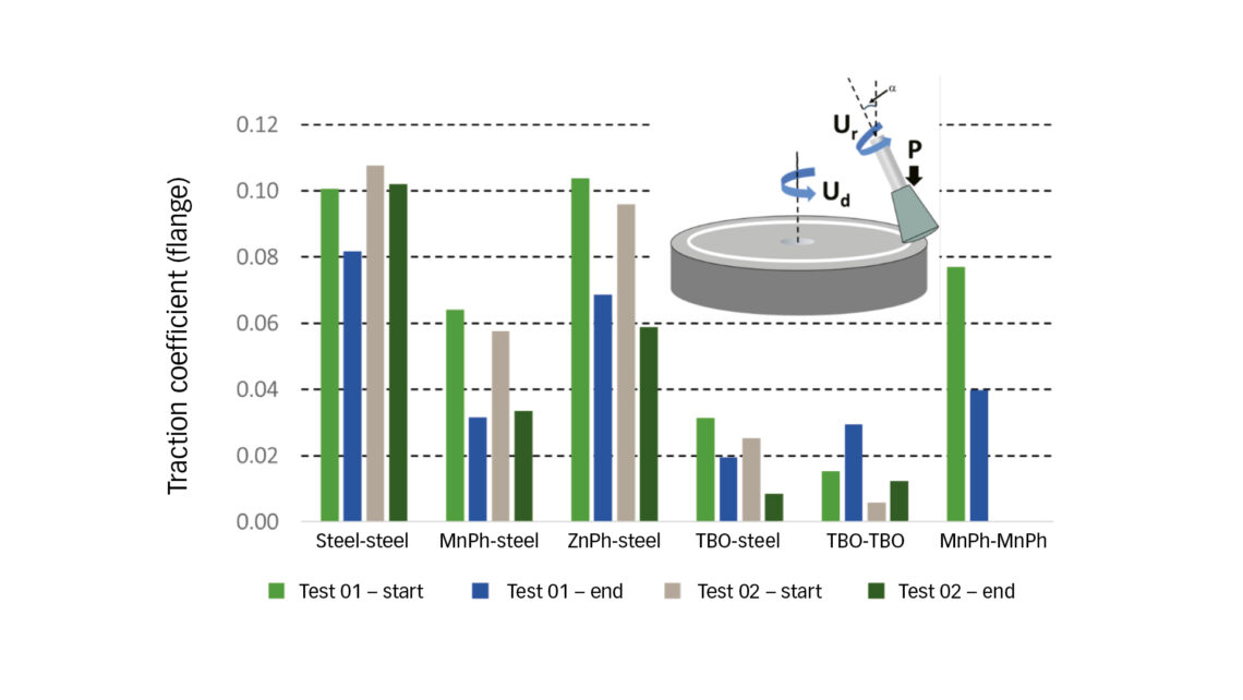
The friction performance in rolling/sliding conditions was evaluated using a Wedeven Associates Machine (WAM) test rig under conditions relevant to cylindrical and tapered rolling element bearings. The WAM rig was used in two different configurations, one simulating a bearing raceway contact, the other simulating a bearing roller-end to flange contact. All tests used a lubricant mineral oil of 32 cSt at 40°C with no EP/AW additives, the temperature was 60°C and the lubrication parameter λ = 0.3.
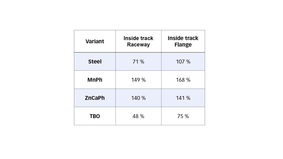
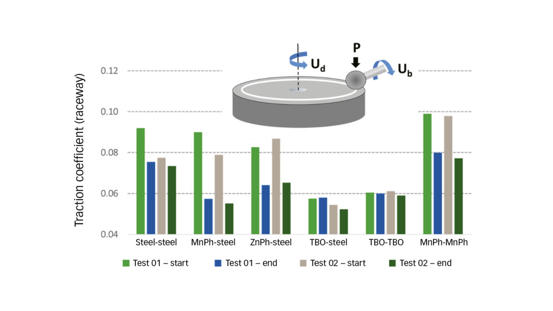
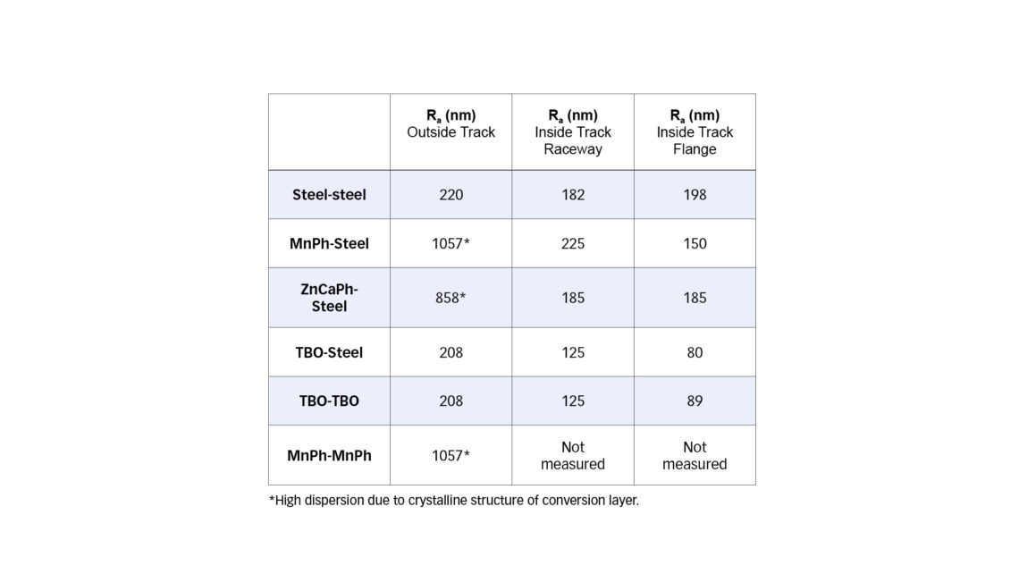
In the raceway (fig. 3) and flange (fig. 4) contact conditions we can observe that, while MnPh and ZnCaPh present a significant drop in friction from start to end of the duration step compared to the steel variant (related to running-in of the conversion layers), TBO presents the lowest friction from the start. The benefits in friction can be compared to roughness inside the running track after the tests (table 2), which is significantly lower for the TBO disk in both the raceway and the flange configuration.
Bearing Friction Tests
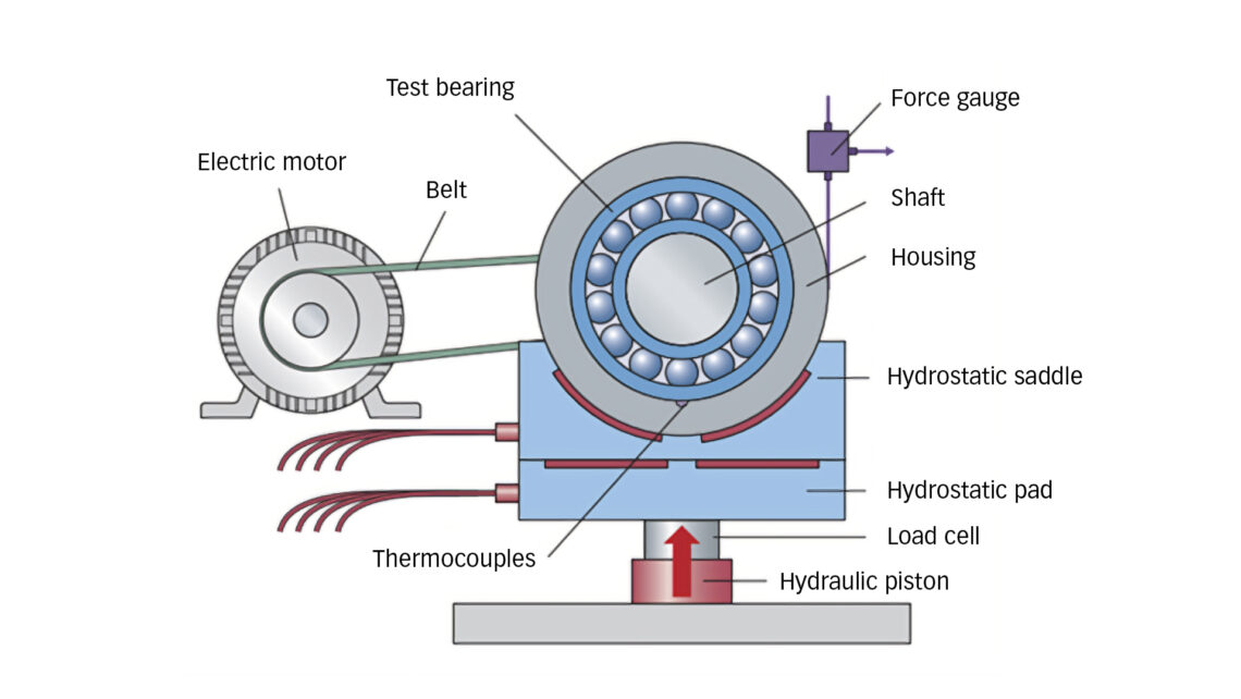
An inhouse test rig (fig. 5) designed specifically to measure bearing friction torque under various speed and load conditions has been used to compare the different conversion layers in conditions as close as possible to typical intercity train wheel-end bearing units. Because wheel-end bearing units are typically double-row units, the tests have been performed with a double-CRB (cylindrical rolling bearing) setup (NU2207 ECP/C3 and NJ 2207 ECP/C3). Cylindrical bearings were selected instead of tapered bearings to facilitate disassembly/reassembly of the roller sets to coat the inner and outer rings. The roller sets have been kept with original rings to maintain C3 internal radial clearance. Prior to testing, each bearing was filled with 2.5 g of a typical railway grease, ensuring the same initial grease distribution.
The radial load has been set to reach contact pressures of 1.3 GPa on the inner ring and 1 GPa on the outer ring. The axial load for the speed cycles has been set to reach 200 MPa on the flange contact. The speed cycle was designed to represent typical linear speeds obtained in intercity railway wheel-end units and also to minimize the effect of grease movements on the measured torque. The axial load cycle was designed to stress the flange contribution yet stay below the maximum recommended axial to radial load ratio.
After a 10-hour running-in, each speed or axial load step of one hour is divided into a 30 minute clockwise and a 30 minute counter-clockwise rotation at the given speed, and the torque was averaged over the last 20 minutes of each. This enabled a correction to any offset in the force gauge, leading to a low standard deviation. Each cycle was repeated at least six times after the running-in, and each test was repeated on at least two bearing sets. In this test campaign, the inner and outer rings were kept uncoated or coated with either TBO, MnPh or ZnCaPh coatings. The rollers were uncoated.
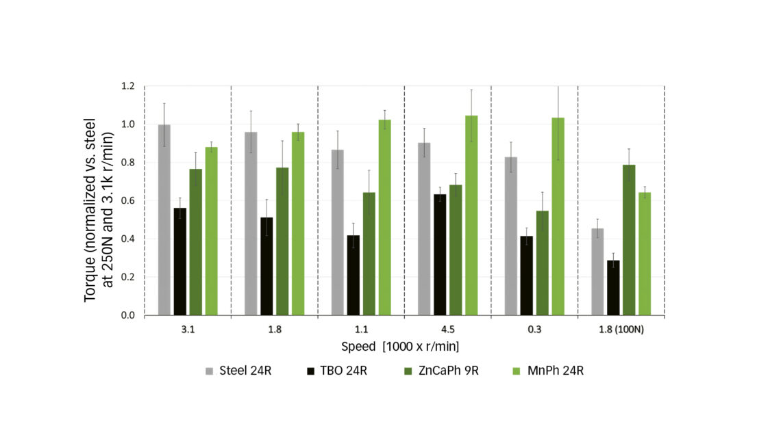
The average torque measured at different rotational speeds on the double CRB setup is presented in fig. 6 for the tests with uncoated steel rings and with the TBO, MnPh and ZnCaPh rings. The average torque is normalized to the one measured in the case of the uncoated rings at 3100 r/min and 250 N axial load. After the speed cycle tests, the roughness of the raceway and flange on the NJ2207 inner rings was measured by interferometry (table 3). The roughness measured was compared to that of the average roughness of the new inner ring raceway.
Fig. 6 shows that the TBO rings consistently lead to the lowest torque, which correlates with observations made on the ball-on-disk experiments. Roughness measurements suggest that the lower torque may come from the running-in and smoothened surface topography on the inner ring raceway and flange (table 3). This may explain why the TBO benefits are somewhat reduced at higher speeds, where the film thickness separating the surfaces is higher.
Final Remarks
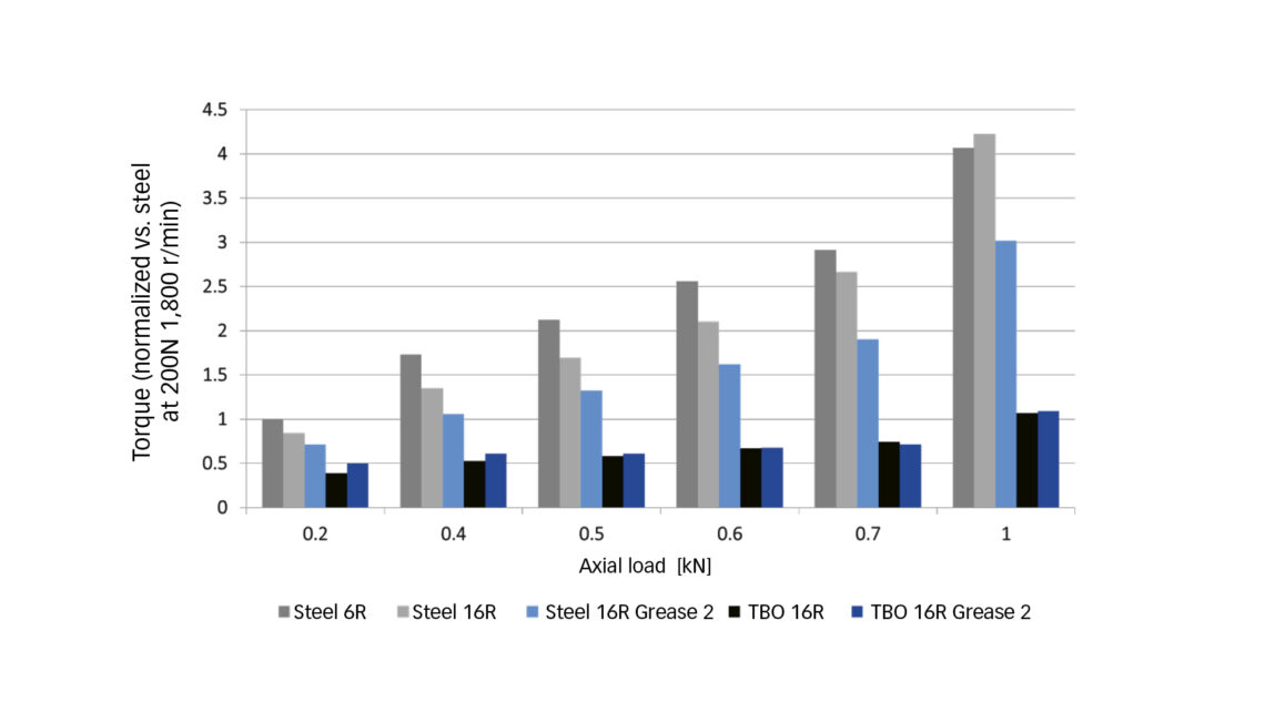
The reciprocating sliding tests, the WAM rolling/sliding tests and the bearing friction tests showed that TBO had optimum friction reduction potential. Under the tested conditions, applying TBO on the disk reduces friction coefficient from 0.08 to 0.06 in the raceway configuration (fig. 3) and from 0.09 to 0.02 in the flange contact configuration (fig. 4), compared to uncoated disks. In the bearing tests with double CRB, applying TBO on the inner and outer rings decreased up to 75 % the bearing torque (compared to uncoated rings) when applying a five-times-higher axial load (hence increase the flange contact contribution) (fig. 7). It seems that a significant part of the benefits of applying TBO to reduce bearing friction comes from the flange contacts where contact pressures do not facilitate running-in (compared to raceway contact pressures).
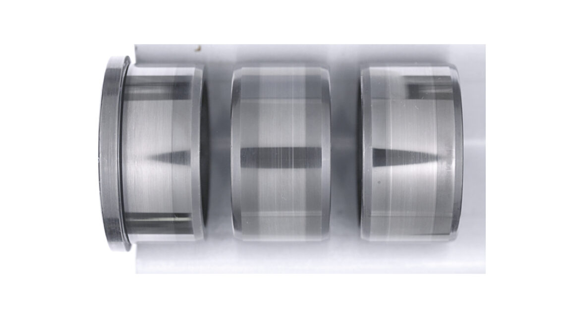
The results also confirm that the benefits obtained by easing the running-in also come with enhanced performance in terms of surface distress and wear when the TBO is applied on the rougher surface [7]. Depending on the operating conditions, the TBO may appear visually black, even after a long duration (fig. 8), and may appear brighter and polished away within the rolling element contact areas. Even if it appears worn off, a thin layer remains with a higher oxygen content and smoothened surface. It is worth emphasizing that, outside the rolling contact areas, the TBO will bring other benefits, such as moderate protection against corrosion, increased lubricant wettability, hydrogen barrier, etc [2].
Further developments to validate, homologate and industrialize the solution for railway wheelset are needed. These additional steps will be taken by the railway engineering and development teams to bring to our customers the most energy-efficient and sustainable solutions.
Contact: Esteban Broitman esteban.daniel.broitman@skf.com
References
- E. Broitman; A. Ruellan; R. Meeuwenoord; D. Nijboer; V. Brizmer, “Comparison of Various Conversion Layers for Improved Friction Performance of Railway Wheel-End Bearings.” Coatings 13 (2023) 1980
- “SKF Coatings Catalogue.”
- E. Broitman, “Coatings to Improve Bearing Performance.” Evolution (2022) 1-7.
- T. von Schleinitz, K. Nentwig, C. Bruckhaus and W. Kachler, “Brünierung: Die alte neue Hochleistungsschicht,” Galvanotechnik, vol. 5, pp. 889-894, 2018.
- ”DIN 50938 – Black Oxide Coatings on Ferreous Metal Components – Requirements and test methods,” Deutsches Institut fur Normung e.V., Berlin, 2018.
- ”ISO 11408: Chemical conversion coatings – Black oxide coating on iron and steel – Specification and test methods,” International Organization for Standardization, Geneva, 1999.
- V. Brizmer; K. Stadler, M. van Drogen; B. Han; C. Matta; E. Piras, “The Tribological Performance of Black Oxide Coating in Rolling/Sliding Contacts.” Tribology Transactions 60 (2017) 557–574.


