Accurate drives for positioning tables
Bonding machines require high stroke frequencies, minimum cycle times and high measuring resolution. The following values are typical for such systems:
The need for accuracy combined with speed is encouraging the adoption of novel drive concepts for positioning table systems.Demands made on driven table systems have been growing constantly in the past few years. Whereas a guiding accuracy of 10 µm and a positioning accuracy of 50 µm were accepted in the past, today’s requirements are for considerably greater accuracy in combination with higher speeds.
These stringent requirements are inducing more and more companies to cease producing positioning tables in-house and to seek manufacturers that can provide complete systems that fulfill their particular requirements.
Selecting systems
Manufacturing high-precision linear guidance systems is a straightforward process, using modern manufacturing methods. Parallelism of as little as 2 µm/m can be consistently produced. The real challenge lies in the final mounting of the system. With some guidance systems using profile rail guides, it is not possible to achieve a running accuracy better than 5 µm per 500 mm travel, even with careful mounting of the system.
Precision rail guides have proved to be a suitable guidance solution for high-precision table systems. They allow a guiding accuracy of 1 µm or better to be easily achieved.
This type of guidance allows very accurate alignment. Subsequent lapping of the guiding tracks can be performed, should this be required for increasing the guiding accuracy. The shortcoming of precision rail guides is that they provide only limited travel. The problem of creeping of cages, occurring under unfavorable operating conditions, was solved by the integration of forced cage guidance. Comparative measurements made on three identical cross (XY) tables, but with rolling element, aerostatic and hydrostatic support, showed that precision rail guides supported on needle rollers achieve guiding accuracies similar to those of aerostatic guides.
On-line compensation, which involves incorporating a laser alignment measuring system, can provide additional accuracy. The deviations of an operating point from the reference straight line due to guiding track deviations, machining forces, weight forces, etc., are recorded during machining and compensated for by means of correction values entered for the different tables.
Drive system selection
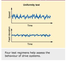
To evaluate the dynamic behavior of drive systems, four methods of investigation were developed for precision applications to provide a good assessment of the system’s overall quality.
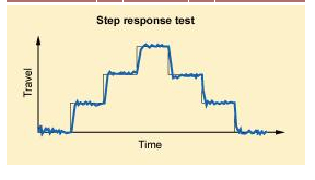
The step response test determines the accuracy of the smallest possible travel increments in the micron range and below. The slides travel forward and backward in small steps. The results enable calculation of the smallest step length with the remaining positioning error being equal to the step length.
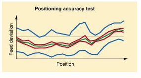
The positioning accuracy test, according to VDI/DGQ 3441, is a standard acceptance test for machine tools for statistically reliable testing of feed drives. The curve of the positioning errors is determined as a function of the traveling distance, split into measuring points and evaluated on a statistical basis.
The uniformity (repeatability) test is a method for determining feed deviations with a constant nominal feed speed. During the travel, the nominal and actual position values are recorded and the feed deviation is determined in the form of a position and speed expressed as a percentage of the nominal speed.
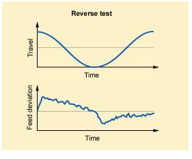
The reverse test determines the feed errors for only one axis with the drive system traveling in a sinusoidal curve. It yields different characteristics of the system, such as start-up behavior, reversing range, uniformity of movement at different speeds or linearity with small signals. Of special interest for evaluation are those areas when the speed changes sign.
Ground ball and roller screws proved successful for operation in the precision range. Results showed that step lengths of 10 nm could be traveled in the step response test. The uniformity test also yields satisfactory behavior with travel path deviations ranging between 0.1 to 0.2 µm. However, the weak point is the reverse test that showed path deviations of up to 3 µm when the speed value passes through zero. If no linear measuring system is used, fitted parallel to the axis of travel, this error can increase depending on the table position.
Drive systems that combine high traveling speed with high positioning accuracy are normally designed as preloaded toothed belt drives. A special design feature allows positioning to be approached without excessive vibration in the drive system. This results, however, in additional increase in cycle time, which for component placement robots for circuit boards implies reduced placement capacity.
Linear direct drives represent a completely new approach, combining the characteristics of highly accurate and highly dynamic positioning systems.
The linear direct drive is normally fitted between the guidance systems to ensure uniform load distribution. A linear measurement system is located as close to the motor as possible to provide exact position measurement. Thanks to the direct conversion of electrical energy into feeding forces, the system obviates the need for mechanical transmission elements, so enabling a rigid control loop to be achieved. Thus, control dynamics are very high, combined with good positioning accuracy and small contour variation. The system accuracy of positioning and repetition are considerably higher than with conventional ball and/or roller screws.
A significant advantage of this system is wear-free operation, independent of traveling speed and acceleration. To achieve economic manufacturing of motor elements, several basic types of three-phase synchronous drives are available. Within each class, they have identical cross sections and the driving forces are determined by their lengths.
When comparing the positioning times of a high-precision toothed belt drive and a direct drive, it turns out that for strokes up to 50 mm, the time from start to approaching the desired position can be reduced by 50%. Maximum speeds of 3 m/s and accelerations exceeding 30 m/s2 were measured.
Such results, however, are only possible when the system is designed and manufactured by a single supplier. The guidance system needs to be adapted to the mechanical requirements of the table and motor systems. Furthermore, the measurement system must be selected in such a way that the specified positioning accuracy and time can be achieved without causing unfavorable operating conditions for the motor. In practice, the function of the entire system depends mainly on the natural frequencies of the mechanics.
Application areas
Most applications for positioning systems with direct drives are in the electronics industry, e.g., in component placement equipment for circuit boards, bonding equipment and testing machines for soldering joints. Another area is mounting equipment for micro components where the high positioning accuracy and speed is considered to be an advantage when compared with conventional drive systems.
Bonding machines require high stroke frequencies, minimum cycle times and high measuring resolution. The following values are typical for such systems:
| Load | 50 – 100 N | |
| Speed | 0.1 – 0.5 m/s | |
| Acceleration | 5 – 20 m/s2 | |
| Position tolerance | +/- 1 µm | |
| Measuring tolerance | 0.1 µm | |
| Stroke | 160 x 160 mm |
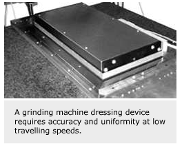
For guidance units incorporated into a grinding machine dressing device, extremely high uniformity at very low traveling speeds is as important as high guiding accuracy. Typical technical data for such units are:
| Load | 1,000 N | |
| Speed | 1 – 10,000 µm/s | |
| Acceleration | 1 m/s2 | |
| Position tolerance | +/- 1 µm | |
| Measuring tolerance | 0.01 µm | |
| Stroke | 50 mm |
Straightness deviations:
| Side | 0.4 µm | |
| Height | 0.7 µm | |
| Reverse backlash | 0.04 µm |
Guidance is achieved through precision rail guides with needle roller and cage assemblies, which are characterized by their high stiffness. The temperature of the primary part located in the stationary table base is controlled with a cooling unit. The entire table is completely sealed with a sealing strip extending around the entire circumference.
In the future it is likely that direct drive systems will be increasingly used in industrial applications where conventional drive systems have reached the limit of their performance.
Hermann Glöckner
SKF Linearsysteme GmbH, Schweinfurt, Germany


