Acoustic emission helps control grinding
Hahn identifies seven strategies for avoiding wheel regenerative chatter:
Acoustic emission is a newly developed method that allows for greater control in the grinding process and the creation of bearing elements with more consistent geometrical properties.Acoustic emission is a technique that can be applied to monitor and control grinding – one of the key processes in the manufacture of bearings and shafts. Researchers at Lidköping Machine Tools, part of SKF, have developed the technology in response to ever-greater demands for high quality and closer tolerance components.
The main research efforts have addressed the need to develop a more stable grinding operation and to gain more information about the state of the grinding zone. Acoustic emission is one method of gathering information about the grinding cycle.
Understanding the problem
Roundness errors and chatter characteristics are important factors in external grinding. All machine parts used in the cutting process affect the final shape of the workpiece. Belts, hydraulics, spindle, grinding wheel characteristics and machine properties all affect the movement within the grinding zone. These can drive the process behavior between stable and unstable cutting conditions. The interaction between the cutting process and the machine tool structure will set the boundaries for the grinding result.
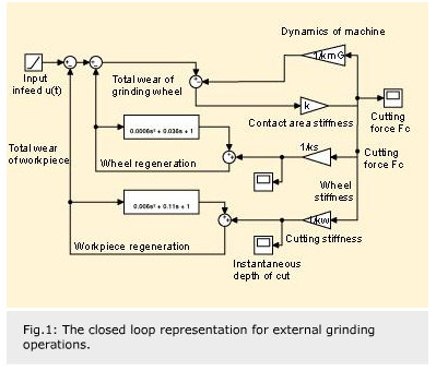
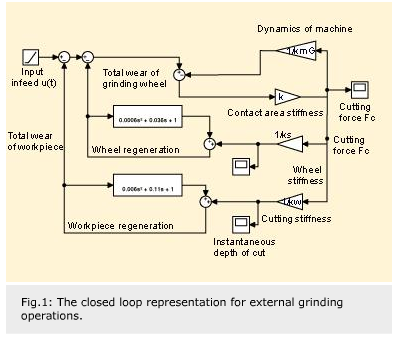
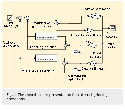
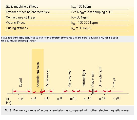
Various researchers, notably R. Snoeys and D. Brown, R.S. Hahn and K. Kounosu, have looked at the basic issues in this. Snoeys and Brown have described a method of understanding the stability criteria for an external grinder (fig. 1). Different stiffnesses for the contact zone, K, machine stiffness, km, stiffness of the grinding wheel, ks, and the stiffness of the depth of cut, kw, are used to create a closed loop representation of the external grinding operation. Experimentally extracted values for the different stiffnesses and the transfer function, G, can be used for a particular process. Typical values are shown in figure 2.
This concept illuminates the cutting forces in the process that result from a chosen infeed, u(t), but it provides little information about the variations in individual processes.
Studies can be made of the machine tool structure to understand how a system works from a roundness and chatter perspective. Classic concepts for grinding theory can also be used in situations where the speed of the workpiece is low enough to give a stable process, yet high enough to optimize the number of produced units.
Generally speaking, a higher structural stiffness together with large damping is preferred for a good dynamic performance during the cutting process.
Concepts for studying chatter occurrence that unite grinding theory and machine tool dynamics can be difficult to design. It is even more difficult to find a concept for continuous monitoring, if one also wants to consider roundness errors with the same method. Acoustic emission has shown some potential to unite the process dynamics with machine tool dynamics in a qualitative manner.
Two types of chatter
In his studies, Kounosu found that there were two types of self-excited chatter vibrations in cylindrical grinding – wheel regenerative and work regenerative – due to the waviness on the periphery. The relative vibration between the grinding wheel and workpiece grows gradually, and the transition from stable to unstable is not obvious from the perspective of changes in vibration level and frequency. Kounosu studied the early generation process of chatter in the transition between these two states and created a model based on the transfer function of the system.
There are many reasons, related to machine settings and characteristics, for the generation of chatter patterns. Hahn has categorized problems such as wheel and spindle balance, geometrical run out, forced vibrations due to pulleys, belts, drive motors. These problems lead to two main categories of chatter, which he also describes as wheel regenerative and work regenerative chatter.
Hahn identifies seven strategies for avoiding wheel regenerative chatter:
- Dress the wheel more frequently.
- Reduce feed rate or force intensity.
- Use a larger grinding wheel for internal grinding.
- Increase the stiffness of the wheel and/or the work support.
- Reduce the width of cut or wheel face.
- Reduce the wear rate of the grinding wheel by using a higher performance grinding fluid.
- Reduce the work speed.
Work regenerative chatter in grinding can be described as a small transient wave that is ground into the workpiece. In one revolution, this wave will become the driving force, causing the system to vibrate again. Unstable conditions can cause a small wavelet to develop and increase around the circumference, giving a non-acceptable grinding result. It has been shown that work regenerative chatter tends to be suppressed if the wheel’s work contact length (lc), is greater than half the chatter length ( ). An expression has also been derived showing the critical parameters for reducing work regenerative effects for higher frequency ranges. From this, three general rules have been developed to reduce work regenerative chatter.
- Use a large grinding wheel diameter.
- Lower the work speed.
- Use softer grinding wheels (this contradicts rules to reduce wheel regenerative chatter).
These parameters affect the high-frequency chatter characteristics but not the low-frequency structural modes of the machine, which is why the lower order lobing problems will remain. In his studies, Hahn also mentions an alternative way of reducing the cutting stiffness (kw). This is shown by the expression:
kw = (vw b) /  w w |
[N/µm] |
where |  w = wheel sharpness w = wheel sharpness |
[mm3/sN] | (where  w = Qw/Fn) w = Qw/Fn) |
vw = work–speed | [m/s] | b = width of cut | [mm] | Qw = material removal rate, | [mm3/s] | (where Qw = vw fr b) |
Lower work speed, narrower width of cut and keeping the wheel sharp (high  w ) would tend to reduce or eliminate chatter.
The problem of increasing the machine stiffness has also been studied. It is not always feasible to increase the stiffness or the damping of the machine. Some solutions to delay or prevent instability phenomena have been suggested.
- Use of controlled forced vibrations.
- Periodic variations of the machine transfer function.
- Application of active dampers.
- Programmed wheel and work-speed variation.
- Periodic variation of grinding forces.
Other stability improvement methods based on geometrical limitations, such as grinding shoes, need to be optimized for maximum mechanical filtering. Selected shoe angles can affect the generation of waves that can be of growing amplitude or highly suppressed.
The stability of the grinding process can be improved if the increasing amplitudes on a workpiece can be suppressed. Some researchers have attempted suppressing chatter growth by changing the work speed continuously. Here, the work speed revolution is kept at a mean value of 500 r/min with a sinusoidal form superimposed. This has an amplitude of 25 r/min and a period of 6 to 10 seconds (i.e. nw = 500 + 25sin ( ). Vibration amplitudes were measured with and without the sinusoidal variation, and the workpieces were measured. It was concluded that the vibration amplitude decreases if a sinusoidal variation is applied. This study also showed that a smaller period (6 seconds) is preferred compared with a longer period (10 seconds).
Using acoustic emission
The application of acoustic emission as a tool for roundness and chatter detection can only be exploited if its potential and limitations are understood. Acoustic emission is of most use in carrying out evaluations in the frequency domain.
Acoustic emission (AE) is elastic waves produced by microscopic deformation occurring in materials as they are stressed. These elastic stress waves are the result of the rapid release of strain energy within a material due to internal structural re-arrangements. Stress waves are transmitted and carried by the material and/or other materials linked together with the AE source. Ultimately this results in a displacement on the surface. A sensor mounted at this point can detect such displacement waves.
This definition of acoustic emission will help in the understanding of the processes that are capable of changing the internal structure of a material. Dislocation motion, diffusion creep, grain boundary sliding and twinning are all well-known mechanisms from material science. These result in plastic deformation. Phase transformations, nucleation of vacancies and fractures are also sources of acoustic emission in a material. Of these, only plastic deformation and fracture are of interest in metal-cutting processes. The frequencies of the signal depend on the workpiece materials and the loading conditions. Such signals range from the conventional acoustic range to MHz. Figure 3 compares the frequency ranges of acoustic emission signals, radio waves and sounds.
Distortion and damping
The acoustic emission signal propagates well through solid material. Acoustic emission waves are either shear or longitudinal. Any internal surfaces, i.e., cracks or inclusions, will distort and damp these waves. A single grain in a conventional grinding wheel will produce an acoustic emission burst propagating through the wheel. Each grain that interacts with the workpiece contributes to the observed AE signal. Because of damping and reflection, distortion of the signal will take place as the signal travels through the media on its way to the sensor. However, frequency-related features in measured signals can be identified. If they are scaled the same way, it is possible to identify process parameters in measured data. This means that a certain process can be monitored and analyzed as long as the signal path is unchanged.
If the conditions between the acoustic emission sensor and the emission source are unchanged, the acoustic emission waves will be filtered (distorted) and damped in the same way. The signal-to-noise ratio of acoustic emissions depends on the location of the sensor. Moving a sensor closer to the emission source strengthens the signal and decreases the noise.
Monitor the cutting variation
The acoustic emission signal is directly generated in the deformation zone of the cutting process and thus provides a reliable way to investigate different stages in the process.
Vibrations of importance, which interact with the grinding zone and influence workpiece quality, are generally in the range from zero to 20 kHz. Multiples of this range and other frequencies can be measured in the frequency range from 20 kHz to 100 kHz, but can be considered as highly damped, i.e., with very low amplitudes. Vibrations above 100 kHz are not likely to interact with the workpiece, due to their extremely small amplitudes.
Why is process information so strong in the acoustic emission signal? Generally, emission ranges up to megahertz frequency are sent out by the plastic deformation from the cutting process. The sensor is optimised to give a distinct characteristic in the frequency window of the hardware used for signal conditioning. This signal from the sensor is then amplitude modul-ated and the AE RMS value is evaluated. Process information is carried by the emission range above the influencing vibration range (zero to 20 kHz). When transmitted in the machine structure, the high-frequency range of the AE signal is not affected by low-frequency vibrations of cutting force variations in the grinding zone. Of course, variations of the cutting force are highly influenced by the vibrational state of the machine and vice versa. This is why the vibrations that influence the grinding zone can be studied with the acoustic emission technique and those that do not affect the shearing of metal will be left out of the signal. This high frequency signal is enveloped and analyzed as an RMS analog signal.
Process stability using acoustic emission
Smaller variations in the cutting zone related to process variations can also be quantified by using acoustic emission as a sensing technique. These are transitions in the cycle where the shape of the workpiece is continuously improving toward a slightly decreasing radial variation and can be identified by a simple approach.
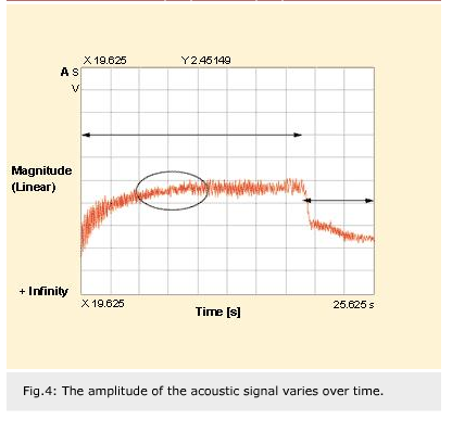
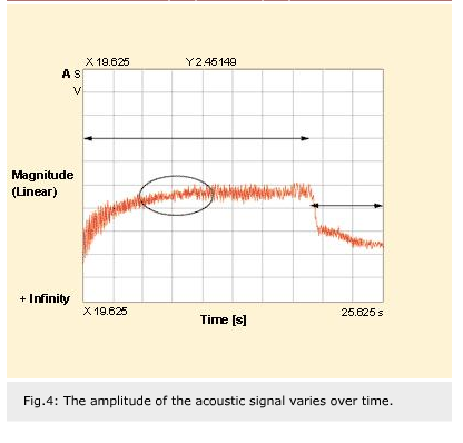
The acoustic emission signal is sensed and processed in the frequency range, which holds the process information. An example in figure 4 illustrates this change at approximately t = 12 to 17 seconds. During this time span, the signal has lower amplitudes, which suggests better cutting. After this interval, cutting variations increase during rough grinding, thus indicating increasing radial variations.
Stability within a grinding cycle
Work regenerative effects are often seen as the primary source of machine tool instability. Extensive work has been carried out on the characteristics of chatter. Shape variations have been researched less avidly, and few published papers have been found dedicated to the issue. This can be explained somewhat by the fact that smaller deviations in measured data have to be correlated. It is, therefore, harder to obtain accurate results from measured quantities when an experimental approach is taken. Force measurements are often not fast enough to be used to register the variation in the grinding zone if the sensors are positioned too far from the actual grinding zone.
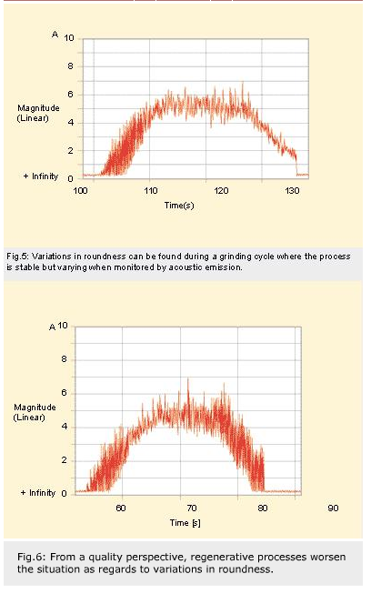
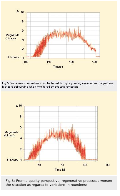
Variations in roundness can be found during a grinding cycle where the process is stable but varying (fig. 5) when monitored by acoustic emission. From a quality perspective, regenerative processes worsen the situation (fig. 6).
Stability within a dressing interval
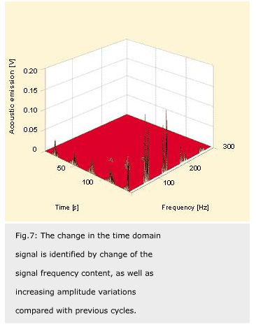
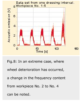
Wheel regenerative effects cause unwanted shaping of the grinding wheel. This has a consequent effect on the dressing interval. The interaction between the wheel and the workpiece can be studied if a time-domain signal is sampled using a frequency range from zero to 1,000 Hz. Uneven cutting conditions will occur if, for instance, a chosen dressing interval is too long. It is more difficult to spot the change in the time domain signal than in the frequency domain. This is identified by change of the signal frequency content, as well as increasing amplitude variations compared with the previous cycles (fig. 7). In an extreme case (fig. 8), where wheel deterioration has occurred, a change in the frequency content from workpiece No. 2 to No. 4 can be noted.
Acoustic emission can be used for quantifying the events in the grinding zone. Quantitative information can be extracted both in the time domain and frequency domain. Using the frequency domain provides data regarding the stability of the process. This can be combined with accelerometer testing during trouble shooting or for identifying small cutting variations during production to control and further improve grinding operations.
Erik Hellström,
Lidköping Machine Tools AB, Sweden


