Axlebridge designs for low-floor tramways
Low-floor tramcars and light rail vehicles offer easy entry for passengers into the vehicle. The Combino® modular tramcar made by Siemens is equipped with an advanced axlebridge developed by SKF.
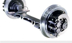
Today most tramcars are designed as low-floor vehicles. This design principle helps passengers to enter the car easily. The Siemens Group, for example, has developed the very successful Combino® modular tramcar and light rail vehicle (LRV) concept. In this design, the running gears are based on a highly sophisticated axlebridge component ( .1) and integrated completely into the Combino car body. Siemens Transportation Systems is one of the leading suppliers to railway systems in the world today.
In the middle of the 1990s, Siemens Transportation decided to concentrate all of its production of bogie components at Siemens SGP, Graz, in Austria. More than 3,000 bogies are produced there yearly, ranging from products for high-speed trains, locomotives, metros, passenger coaches to light rail vehicles and low-floor tramcars.
The Combino concept
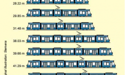
The modular Combino concept was developed by Siemens for low-floor tramcars and light rail vehicles. All these vehicles have a low-floor design over 100 % of their total length. This product platform provides the opportunity to adapt the principal car design to the particular requirements of the tramway operators of various cities with regard to different vehicle lengths and widths by variation only of the size of the different modules and the arrangement of motor and trailer bogies ( .2).
More than 600 Combino cars have been sold since 1997 to 16 cities in nine countries. Siemens is the market leader worldwide in low-floor tramway vehicles and has a market share of about 40 % for all low-floor trams bought worldwide during the past five years. More than 360 cars are in revenue service. Some 70 % of Combino cars are produced for standard gauge (1,435 mm) and the rest for a one-metre gauge.
Modern tramcars and light rail vehicles with 100 % low-floor design usually have a floor height of around 350 mm above the top of the rail over the total length of the car, without any steps or ramps inside the vehicle. As a consequence, there is a very limited space to accommodate propulsion and running gear (bogie) components. In combination with the increasing performance requirements for these vehicles, development targets are very challenging.
As well as the car itself, the Combino bogie SF 30 is designed to provide a high level of modularity. Both powered and non-powered trailer running gears are equipped with a cranked stub axle to allow 100 % low-floor design without having any steps or ramps. The powered running gear is equipped with a hollow shaft, which is connected to the wheel with an elastic spider coupling. The traction torque is transmitted to the wheels from a longitudinal traction motor and a gear drive on both ends.
At the non-powered axle, a flange brake disc is mounted to the wheel with two guiding rods mounted to support the axle during braking. In addition, on the stub axle of both executions (powered and non-powered), a magnetic track brake for emergency braking is mounted.
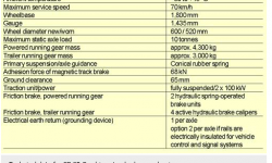
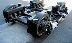
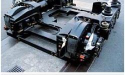
For the Combino cars, which are tailored for the requirements of the operators at Amsterdam and Melbourne, Siemens SGP requested a completely new, more sophisticated axlebridge generation with more advanced features ( .3, .4and table 1), including:
- The same interface to different systems of rubber suspended wheels, to allow modularity on the stub axle;
- Lower weight;
- Reduced maintenance;
- The same interfaces to the rest of the bogie design; and
- Logistic solution advantages.
Axlebridge design
The original axlebridge used for previous applications was a combination of two forged pieces connected to a rectangular tube by welding. SKF started with feasibility studies for different manufacturing concepts of the axlebridge component. After evaluating several potential solutions, a cast steel component was finally selected, offering both a high level of reliability and lightweight design possibilities. The design optimisation was carried out in close cooperation with Siemens SGP and the suppliers of wheels, couplings, earth return and brake systems, as well as with the cast and machining subcontractors.
The calculation started with a reversed engineering process and a finite element method analysis of the existing design ( .6). A longer process was started to optimise the proposed new design generation, step by step. The validation of the vibration and stress calculation was done by an independent institute through fatigue testing over 10 million load cycles, according to the UIC (Union Internationale des Chemins de Fer) 615-4 standard.
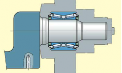
The heart of the axlebridge is the integrated bearing system. In principle, there are two different applications that cause specific load cases:
- Motor running gears with longitudinal suspended traction motor and gearboxes on both sides, driving one wheel pair situated on the same rail. For this application, a smaller and a larger tapered roller bearing is applied.
- For the trailer running gears, a pre-lubricated and sealed tapered bearing unit was selected ( .7).
Earth returns are required to allow the electric passage from the vehicle body via the bogie and wheels up to the rails. In some cases, two earth returns are required from the operator, especially if the two rails are electrically insulated for the vehicle control and signal systems. To protect the bearings from passing electrical current, and to avoid damages to the rollers and raceways, the well-proven INSOCOAT® execution can be selected as an option in both cases. These bearings have a ceramic coated outer ring and are a most economic and reliable solution.
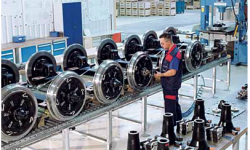
SKF delivers a ready-to-mount subassembly to Siemens SGP, including the axlebridge with the integrated bearing system and mounted components such as wheels, couplings, earth return and brake system. This solution helps Siemens SGP achieve savings in its logistic system because of much easier handling ( .8).
Applications
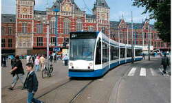
The Amsterdam Transit Authority GVB has ordered 155 Combino type low-floor light rail vehicles from Siemens. This is not only the biggest Combino order received to date by the Transportation Systems Group of Siemens, but it also marks one of the most significant bid successes for low-floor LRVs worldwide. The first unit was delivered to the Dutch operator in November 2001, after a five-week test phase at the Siemens Wegberg-Wildenrath Test Centre ( .9). Three units then followed every two weeks. This fast pace of delivery was made possible by Combino’s underlying modular design – a “construction kit” using service-proven components.
The frequency of service between the major urban traffic hubs during rush hour will be as high as every two to three minutes. The maximum attainable speed is 70 km/h. With a length of 29 metres, this Combino type offers seats for 67 passengers and standing room for 120. The number of cars in service in Amsterdam is about 70.
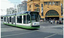
The Australian operator of the Melbourne “Swanston Trams” placed an order for 59 low-floor Combino trams, 38 of them three-sectional and 21 five-sectional. Siemens was also awarded a service and maintenance contract for these trams covering an initial period of 15 years. The first trams entered service in 2002.
The Combino units for Melbourne’s line are 20 or 30 metres long and are designed to operate in double-ended mode ( .10). During peak hours, the Combino offers seats for up to 54 passengers. The new trams are a key element in increasing transportation capacity while also enhancing the general attractiveness of public transport.
Outlook
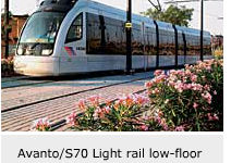
Recently Siemens developed a further product platform, called Avanto/S 70. This new LRV product family has a low-floor section of 70 % over the vehicle length. Avanto/S 70 vehicles are designed for a maximum speed of 106 km/h. The first cars will go into service in Houston, Texas, in the United States, in January 2004. There are two further contracts for Paris and San Diego, California. During the past year, a further similar axlebridge design for the trailer bogie was developed from SKF together with Siemens SGP to meet the increased requirements ( .11).


