Bearing the biggest bascule
The south bank of the River Maas, in the heart of the Dutch city of Rotterdam, is the site of an ambitious urban regeneration scheme known as Kop van Zuid.Providing the key link to the 125-hectare site is the new Erasmus Bridge, completed in September 1996 (see article in Evolution 2/96). This impressive design provides the major above-ground link with the inner city on the north bank. The aesthetics of the bridge design are important as they set the atmosphere and character of the urban expansion on the south side. So, to satisfy both aesthetic and technical considerations the choice of construction is three bridges in one – a 280 m main-span, cable-stayed bridge; composite steel concrete side span viaduct, and bascule bridge. The technical design of the Erasmus Bridge was carried out by the City of Rotterdam’s Public Works engineering department.
The south bank of the River Maas, in the heart of the Dutch city of Rotterdam, is the site of an ambitious urban regeneration scheme known as Kop van Zuid.Providing the key link to the 125-hectare site is the new Erasmus Bridge, completed in September 1996 (see article in Evolution 2/96). This impressive design provides the major above-ground link with the inner city on the north bank. The aesthetics of the bridge design are important as they set the atmosphere and character of the urban expansion on the south side. So, to satisfy both aesthetic and technical considerations the choice of construction is three bridges in one – a 280 m main-span, cable-stayed bridge; composite steel concrete side span viaduct, and bascule bridge. The technical design of the Erasmus Bridge was carried out by the City of Rotterdam’s Public Works engineering department.
The architectural design of the bridge provided a number of challenges, not least the cable-stayed bridge that includes the asymmetric knee bend, 139 m high pylon which provides the ambitious landmark of the project. Also, practically every piece of steel plate is a unique shape and dimension to create an enormous jigsaw of structural elements. As the structure contains virtually no straight angles, it would have been impossible to create and build the bridge without the help of modern computer technology including 3-D, computer-aided design and calculation systems as well as numerically operated flame-cutting machines.
Urban changes
For many years the City of Rotterdam has had the world’s busiest harbour in terms of volume of goods shipped. Post-war growth has resulted in the main harbour’s activities moving further seaward. The largest oil tankers, for example, are usually moored in the recently created, major industrial areas of Europort and the artificial offshore peninsula, Maasvlakte. Both these areas have become centres of economic activity while older harbour sites, closer to the city centre, have lost their usefulness. It is these sites that have the potential for urban renewal.
The first serious plans for “Kop van Zuid” were presented in 1987. This called for the construction of high-quality office accommodation along the waterfront. The strategy for Kop van Zuid has been to put the publicly-funded infrastructure in place before other construction work occurs. This is the opposite approach to that taken when the London Docklands regeneration scheme was begun in the 1980s. By the time the first inhabitants move in, a major network of public transport facilities – bus, tram and metro – will be available.
A key element in the new infrastructure is the new north-south traffic axis, which includes the Erasmus Bridge. The new bridge deck is 33 m wide and will carry twin tram lines, two double traffic lanes plus free lanes for cyclists and pedestrians on both bridge sides. Although major harbour activities lie closer to the sea, a number of shipbuilding and maintenance industries still exist upstream of Rotterdam. As a consequence, the harbour authorities require a 50 m free navigational width. This is provided by the bascule bridge.
Bascule bridge
It was the functional specification that governed the complex technical design of the single-leaf, moveable bascule bridge – unlike the cable-stayed bridge.
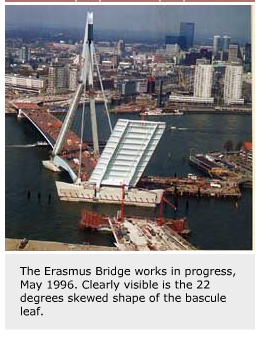
Apart from the sheer size – the 52.3 m x 35.8 m leaf dimensions makes it the largest of its kind in the world – there are other features that make the bascule unique.
The main “eye catcher” is the oblique, 67° crossing of shipping and traffic. The bridge deck has a parallelogram shape and leans 19 m sideways in its open position and reaches a maximum height of 63 m above water level.
The large in-situ cast concrete bascule basement – 60 m long and 31m wide – houses the hydraulics and counterweight. This is used to anchor the two 4,500-tonne main-span, back-stays reaction force. The cellar floor is 13 m below water level and is made of 10 m thick concrete to prevent the basement from floating.
The two main girders are shaped as plate girders on the front elevation and as box girders at the rear elevation. They have a maximum height of 6.8 m close to the main bearings. Additional box girders for the rear cross girder (located at the sideways twist of the main girders) and for the counterweight girder result in a closed square of box girders that provide a large resistance to the enormous tilting moments.
Member torsion is increased by the eccentricity of the main rotation supports and the position of the counterweight. The counterweight has a lateral eccentricity placed opposite to the bridge obliqueness in order to provide an equal distribution of the weight responses in the main rotation supports. This allows for optimisation of the main supports.
The bridge dead-weight results in a 300 mm vertical bending displacement at the front of the bridge and a 90 mm distortion between both front supports. These deformation figures were arrived at by detailed finite element analysis and subsequently compensated for during fabrication by building the bridge in a complex bending and twisting shape.
Rail transport on the steel bridge demanded special attention. The rail is embedded in a specially developed, poured rubber material in order to reduce sound emission. This avoids steel-to-steel contact and results in a reduction of sound by at least 5dB(A). To allow vertical alignment at the bridge-front, rail interruption, the forward cross member is pre-stressed downwards by 100 tonnes after bridge closure. The resulting 25 mm pre-stress displacement exceeds temperature or mobile-loading deformations, ensuring correct vertical rail alignment. Due to the passage of public transport, the bridge has to be able to operate quickly – opening in only 120 seconds and closing within 135 seconds.
The chosen driving mechanism of the bridge is essentially similar to most other modern moveable bridges in Rotterdam. The bridge operation system used is a plc-controlled, remote-operated, open-type hydraulic system with controlled-pump adjustment. Four hydraulic cylinders (stroke 6.8 m; bore 0.6 m; piston rods 0.4 m) generate a maximum driving moment of over 100,000 kNm to resist wind-induced forces up to 7 Beaufort. In case of higher wind speeds the start of the bridge opening is automatically blocked. Two separate electro-hydraulic units, with 440 kWh installed power, each allow the bridge to move at the pre-determined high speed. Spherical plain bearings GEP 360 FS are used for the cylinder supports. These bearings enable compensation for mounting inaccuracies.
Fail-safe analyses were executed to optimise the reliability of the bridge operation. As a result, a number of fail-critical electric and hydraulic components, such as the main power supply, hydraulic-units and cylinders were installed in parallel. This layout allows bridge operation to continue during emergencies or maintenance.
A major problem that had to be solved was the stabilisation of the bridge movement, since the cylinders act as huge springs for the large dynamic driving forces. Numerical simulations and tests at the fabrication site were executed to optimise the hydraulic parameters for the bridge response. To avoid problems at the end of the opening and closing sequences of the bridge, buffers and dampers were installed to avoid vibrating or shaking bridge movements and for further speed reduction.
Rotation supports
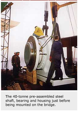
For the bascule, unusual single-sided, cantilevered-flanged axle supports were used, as the more commonly used symmetric through axle with double-sided bearing supports turned out to be unfavourable. Calculations showed that the latter would act as a constraint for the large tilting moments, resulting in a significant increase in support reactions. The 2 m diameter steel axle flange is connected to the outer web of each main girder by 66 high strength M48 bolts. To spread the reaction forces in the main box girder, a large diameter tube was applied between both webs.
The two bridge bearings have to carry the 1,500-tonne bridge weight, the 1,000-tonne counterweight and a maximum of 1,600-tonne reaction force from the four cylinders. The SKF GEP-FS series maintenance-free spherical plain bearings satisfied the high quality and technical demands of the Public Works Rotterdam. The main supports were designed in close co-operation with SKF Nederland BV and SKF Gleitlager GmbH.
The choice of optimal bearing size was governed by the required life corresponding to a sliding distance of over 400 km, the requested 1 mm friction diameter reduction over lifetime (including the SKF LGEP 2 grease) and the stress in the steel axle. The chosen GEP 1000 FS units, with a sphere diameter of 1,312 mm, are the largest ever used for this type of application. They are particularly suitable for single direction loads, alternating loads with superimposed high frequency vibrations and relatively high axial loads. To cope with temperature expansion only one bearing was axially located.
For the non-locating bearing an additional cylindrical sliding bushing was added for the -10 to +10 mm axial displacements. Axial steel-to-steel sliding was considered inappropriate due to the higher friction and the stress levels in the large diameter axle, made of high strength 34CrNiMo6 steel with a guaranteed yield strength above 500 N/mm2. To allow for fabrication, the non-locating spherical plain bearing outer ring had an unusual axial split.
The bridge rotation may take place by the cylindrical or the spherical sliding layer since both layers were made with identical sliding materials and thicknesses. The applied glass fibre reinforced polyamide sliding material is lubricated with SKF LGEP2 grease and combines a low friction coefficient with a high resistance to corrosive influences and contaminants. The low friction coefficient is of special importance because bearing friction results in unfavourable constraint reactions. For example, a 0.15 friction value results in a 300-tonne horizontal axial reaction force between both bearings for a bridge expanding due to a temperature rise.
Particular attention had to be given to avoid local stress concentrations and fretting in the heavily-loaded steel axle. This was achieved by smoothly curving the axle, by applying a spacer sleeve and by using tight machine tolerances for the shaft (m6) and for the housing bore (K7). To allow for future dismounting of the bearing, the axle surface was provided with grooves connected to internal channels for oil injection. At the factory site the bearing was mounted into the pre-heated housing prior to instalment of the nitrogen cooled steel axle.
The Erasmus Bridge was completed in September 1996. After the installation of the pylon, the last deck section of the cable stayed bridge and the installation of the bascule, the testing of the bridge driving system took place during summer. It was the last phase of calibration for the many computer simulations and calculations that, to a major extent, governed the technical design of the bridge.
Jaco H. Reusink,
Engineering Department, Public Works,
Rotterdam, The Netherlands


