Compromise-free self-aligning bearing system
A novel combination of two bearing types offers equipment designers increased reliability and performance.
SKF designers have created a new self-aligning bearing system that incorporates a CARB® toroidal roller bearing as the non-locating bearing and a double row spherical roller bearing on the locating side. This arrangement offers significant cost reduction through a leaner design and improved productivity. The importance of the development becomes clear when you consider typical application conditions and traditional bearing arrangements and their limitations.
In typical industrial equipment applications, rotating shaft systems are generally supported by two rolling bearings, one at each end of the shaft. In addition to providing support for radial loads, one of the bearings, termed the locating or fixed bearing, has to position the shaft axially with respect to its supporting structure and to carry any axial (thrust) loads that are imposed on the shaft.
The other bearing, the non-locating or floating bearing, also carries radial loads but needs to accommodate axial movement to compensate for:
- thermal elongation and contraction of the shaft or structure with temperature variations;
- manufacturing tolerances of the structure; and
- positioning tolerances resulting from the assembly of the machine.
Traditional compromises
Normally designers, faced with traditional bearing arrangement options, have been forced to make compromises that do not lead to optimised performance.
The classical bearing arrangement employs double row, self-aligning ball or spherical roller bearings for both bearing positions.
It is a simple, robust arrangement that can withstand radial and thrust loads. This bearing combination can also easily accommodate the misalignment typically imposed through machining and assembly tolerances, thermal distortion or deflection under load. There are, however, consequences as a result of using self-aligning ball bearings or spherical roller bearings in the non-locating position. The non-locating bearing must slide axially, usually inside the housing, to accommodate shaft expansion and contraction.
To obtain axial movement at the non-locating bearing, one of the bearing rings must be mounted with a loose fit. Normally this is at the outer ring in the bearing housing or machine casing. There must also be sufficient axial space provided for the intended movement.
Frequently this loose fit compromises the overall design of the machine because, under certain load conditions, the bearing ring may spin and damage the housing, accelerate wear and increase vibration. Also, the shaft is supported less rigidly in the radial direction. This all contributes to additional maintenance and repair costs.
Causes of failures
If a loose fit is needed for axial movement of the non-locating bearing, then during operation, this fit needs to be maintained. This is not as simple as it sounds. For example, at start-up, machine components must heat up to normal operating temperature. The bearing’s outer ring usually expands faster than the housing bore. This different rate of expansion can eliminate clearance and restrict axial movement.
If the bearing housing seating form is not within specification for various reasons such as distortion due to load or thermal effects, then the bearing ring will be held in place and will be unable to move easily to accommodate the required axial movement. Also, the wear process from the loose ring under unfavourable load conditions can also create a condition known as fretting corrosion which can effectively “rust” the bearing ring in place.
If for any reason the non-locating bearing ring cannot move, then both bearings become axially preloaded. This means that as the shaft or structure changes temperature and length, very high axial loads are generated between the two bearings.
Influence of friction
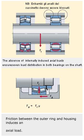
A more general but less recognised consequence of a loose-fitting bearing is that there is always a certain amount of friction between the loose bearing ring and the housing (or shaft) seating. For the shaft to expand or contract in the axial direction, it must first overcome the frictional resistance at the sliding contact. This resistance has the magnitude, Fa = Frµ , where Fa is the axial force, Fr is the radial load carried by the non-locating end bearing and µ is the coefficient of friction between the loose bearing ring and the housing. For steel-steel and steel-cast iron interfaces, values for µ are typically around 0.12 – 0.16. Both bearings are, therefore, subjected to an additional thrust load, equivalent to several percent of the radial load. As a result of these internal thrust forces, the load distribution within the bearings is adversely affected, with each row of rolling elements carrying a different load.
Unstable load conditions
In cases with relatively high speeds, the load distribution can be variable and unstable. Imagine the inner ring of one bearing being slightly crooked on the shaft relative to the true axis of rotation. This is a common situation, typically resulting from machining inaccuracy of the shaft, deflection of the shaft, a combination of tolerances of shaft, adapter sleeve and bearing ring and/or mounting inaccuracy.
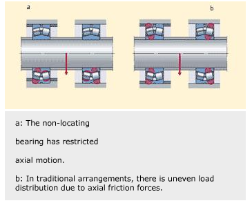
As the inner ring rotates, it performs a very small “wobbling” motion, which imparts a small axial oscillation to the shaft. This oscillation is then transmitted to the inner ring of the second bearing in the shaft system. As the inner rings rotate, they move back and forth with a frequency equal to that of the shaft rotational speed. This results in the bearings’ four rows of rolling elements being alternately loaded and unloaded, or the amount of load experienced is changed. In some cases, the axial motion is transmitted to the outer ring of the non-locating bearing, bringing about axial “scuffing” or fretting wear in the housing.
Typical results of this uneven load distribution can be generalised according to applications. In high load applications, there are increased internal stresses, elevated temperatures, impaired lubrication, accelerated bearing wear and reduced bearing fatigue life.
In high-speed applications, there are high operating temperatures, alternating acceleration and deceleration of the roller sets with fluctuating load distribution, high forces on the bearing cages, increased rate of wear, high vibration and noise levels, rapid deterioration of grease, poor performance in low-load situations and general reliability problems.
These factors occur, to a greater or lesser extent, in all such bearing arrangements, even when the components are new and tolerances are within specification. If situations outside normal friction occur where movement of the non-locating bearing ring is prevented then the situation is equivalent to having a very high coefficient of friction at the non-locating bearing, and the adverse effects during operation are correspondingly severe.
New approach
By applying a different bearing arrangement, many of these potential operating difficulties are avoided to provide reliable operation with improved life. As stated, the new arrangement is to use a CARB toroidal roller bearing as the non-locating bearing in combination with a double row spherical roller or self-aligning ball bearing as the locating bearing.
The bearing arrangement can accommodate both misalignment and axial adjustment internally and without frictional resistance. Also, there is no possibility of generating internal axial forces in the bearing system. Thanks to the ideal interaction between the two bearings, the applied load is always distributed consistently and in the assumed theoretical manner between all load-carrying elements.
The design characteristics of both bearings in the new system are fully exploited. They avoid the need to make compromises in the arrangement, and so deliver increased performance and reliability. Designers can optimise bearing selection and machine construction. Depending on the machine and application, the benefits of the new SKF bearing systems include:
- safer, more optimised designs;
- increased bearing service life for both light and heavy loads;
- extended maintenance intervals;
- lower running temperature;
- lower vibration and noise levels;
- greater throughput of the machine;
- same throughput with a lighter machine; and
- improved product quality/less scrap.
The toroidal bearing is a new design for a non-locating element that helps eliminate the need to make compromises in shaft/ bearing systems. The design takes its name from the curvature at the contact surfaces within the bearing. The toroidal roller bearing has a single row of long rollers with a slightly curved profile. The internal design enables this bearing to accommodate axial movement internally, like a cylindrical or needle roller bearing, without any frictional resistance. This avoids the need for a loose fit, eliminating its disadvantages as explained. There is no possibility for generating additional axial forces between the two bearings on the shaft.
In addition to the elimination of all the axial interaction between the bearings, the roller and raceway profiles in the roller bearing are designed to adjust automatically the roller position inside the bearing so that the load is distributed evenly along the roller contact length, irrespective of any misalignment. This means that there is no possibility for high edge stresses, so the bearing always operates at the optimum stress level and, therefore, achieves its theoretical fatigue life under all conditions.
The combination of the self-aligning properties and the frictionless axial adjustment ensures that the load is distributed as evenly and consistently as possible over all the rows of rolling elements in both bearings on the shaft. This means that stresses are low, temperature is minimised, maximum fatigue life is always achieved and the chances of vibrations and cage damage are reduced. In addition, the risk of worn out housings due to spinning rings can be eliminated because tight fits for both rings can be used for all the bearings in the system.
Downsizing reduces costs
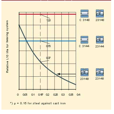
In addition to performance improvements, operating cost reductions and increase in productivity provided by the CARB/spherical solution, there are other benefits to be gained. With CARB as the non-locating bearing, there are no internally generated thrust loads i.e. Fa = 0 for both bearings. In traditional bearing arrangements there are thrust loads, Fa = Frµ , for both bearings. From this, it is simple to calculate the difference in fatigue life obtained in each system. In cases where the life of a conventional arrangement restricted a machine’s performance, substituting a toroidal roller bearing at the non-locating position could significantly extend service life.
Where a conventional arrangement provides adequate service life but from practical experience may be over-dimensioned to allow a safety factor against unfavourable load distribution, using the new bearing system design with smaller bearings in both positions can often still achieve the required life. So there can be significant opportunity to use smaller, less expensive bearing assemblies without the risks of failure associated with axial pre-loading and general lack of axial freedom. Cost benefits are also generated through the consequential size and weight reduction of other structural components.
The potential savings of a smaller bearing, and resultant smaller housing, seal and adapter sleeve assembly at each end of the shaft, includes:
- bearing assembly purchase prices;
- bearing assembly weight;
- shaft diameter and length reduction resulting in material cost and weight savings;
- support structure size and weight;
- production time savings relating to the possibility for less stringent machining and assembly tolerances;
- reduced transportation costs as a result of decreased overall machine weight;
- reduced friction losses result in less heat generation, allowing higher speeds and, therefore, greater efficiency/productivity; and
- reduced temperatures allow increased relubrication intervals and reduced greasing costs.
Overall, there are clear and powerful arguments for the adoption of the new bearing arrangement in rotating shaft applications.
Darren Kenworthy
SKF Sverige AB, Göteborg, Sweden


