Development of traction motor bearings
New generations of traction motor bearing units have evolved to meet more exacting customer requirements.Cylindrical roller bearings remain at the heart of traction motor bearing applications. SKF, the market leader in this application, has a long history of improving technology associated with cylindrical roller bearings. Indeed, the SKF catalogue of 1922 (fig. 1) shows just such an application.
New generations of traction motor bearing units have evolved to meet more exacting customer requirements.Cylindrical roller bearings remain at the heart of traction motor bearing applications. SKF, the market leader in this application, has a long history of improving technology associated with cylindrical roller bearings. Indeed, the SKF catalogue of 1922 (fig. 1) shows just such an application.
Continuous improvement of traction motor bearings
Although improvement to traction motor bearings has been a continuing process over many years, there are a number of developments that are particularly relevant to modern bearing designs for traction motor applications. These are as follows:
- The internal design of cylindrical roller bearings optimised to the E design with greater numbers of larger rollers, to increase the load carrying capacity and extend the nominal life. This change took place around 1960.
- Modifications made to the design of the roller end/guide flange contact area to improve lubrication of the contact zone – also known as “open flange design”. Cylindrical bearings of this design have increased axial load carrying capacity which is a distinct advantage of the locating cylindrical roller bearing. This design, named EC, was introduced in 1981.
- New microgeometry introduced, based on rollers with logarithmic profile. Edge stresses are minimised, with the load evenly distributed over the roller length. At the same time these bearings will accommodate a certain degree of misalignment, commonly occurring on the drive side of an arrangement. These were introduced in 1984.
- SKF New Life Theory introduced, where improved materials and superior machining of contact surfaces are taken into consideration and where there is total separation of the surfaces by a hydrodynamic lubricant film. This means low friction, low operating temperature and reduced wear. The SKF New Life Theory published in1989 is also a useful tool for downsizing and increasing reliability (figures 2 and 3).
- New cage designs introduced – plastic cages for smaller and medium size cylindrical bearings for traction motors, with improved wear characteristics and reduced friction; and optimised brass cages for medium and larger bearings, particularly for heavy load conditions.
- Electrically insulated traction motor bearings introduced, based on plasma spraying technology. These are protected against damage from electric current which can seriously impair the life of a bearing.
Effect of AC traction motors
As applications become more sophisticated, more functions need to be packed into the space available. More demands are placed on the development of new materials, on improved product engineering and production, and on continued research for better mathematical modelling and other techniques to improve the performance and life of systems and components.
In traction motors applying the AC principle, space for bearings is restricted. Downsizing principles need to be applied to allow high maximum speeds. This demands greater integration of adjacent components into the overall bearing system, in order to meet the desired and increasingly stringent specifications. Coupled with this, customers are also looking for complete solutions for greasing, sealing and electrical insulation.
AC motors allow the development of traction motors with higher rotor speeds, greater compactness or increased power for a given size. Higher radial loads, especially those acting on the drive-side bearings, result from the increased motor torque derived from the increased traction power.
Higher axial forces act on the locating bearing because of the use of helical gearing and increased helix angles. This optimises gearbox design and efficiency, reducing size and minimising noise.
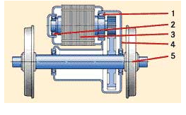
AC traction motors have led to the introduction of oil-lubricated bearings, particularly at the drive side (fig. 4). This reduces the overhang effect by reducing the distance between the pinion and the drive-side bearing. This causes a reduction of the resultant radial load and allows the use of smaller bearings with higher speed ratings. Oil lubrication also allows higher speed ratings than grease lubrication.
Drive side traction motor bearing arrangements which form part of the gearbox arrangement (fig. 5) eliminate the overhang effect completely and reduce the supporting loads. As part of the gearbox arrangement, these bearings are oil lubricated and are suitable for relatively high rotor speeds. Designs of this kind are in use for high-speed trains, locomotives and mass transit vehicles.
In addition, manufacturers and operators are looking for reduction in maintenance and longer re-greasing intervals, and in some cases going even as far as no re-greasing between overhauls. Service intervals can now be extended, sometimes to more than one million kilometres of operations. In addition the maintenance process itself has to be simplified. This included the initial mounting during construction.
Basics still apply
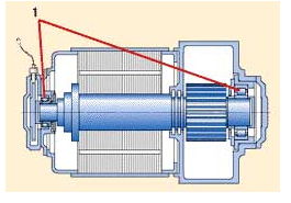
Despite these changes, traction motor bearing design still relies mainly on the basic configuration of two cylindrical roller bearings. As in other vehicle applications such as trucks and cars, the tendency is now towards greater integration of components and more sophisticated electronic sensing and control systems.
SKF has developed two principal designs for different bearing arrangements in traction motors.
TMBU for the non-drive side
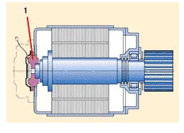
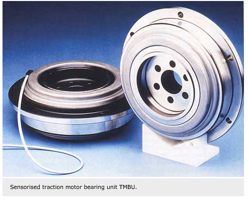
The traction motor bearing unit for the non drive side (fig. 6) which supports radial and axial load has to be flanged on the rotor shaft and on the traction motor bearing shield. This design can incorporate all necessary sensing functions as well as electrical insulation. This unit is a “ready-to-mount” product which requires no further adjustment.
The opposite side bearing arrangement for this configuration can be achieved using an oil-lubricated cylindrical roller bearing. This supports only the radial load and is suitable for higher speeds. It does not require the re-greasing procedures of previous grease-lubricated arrangements.
The customer benefits of this design are:
- less space, lower mass and fewer parts
- it is suitable for operation at higher speed
- easy mounting procedures
- reduced maintenance, and extended maintenance intervals
- fewer failures
- improved service life through increased cleanliness
- reduced life cycle cost
- clear system responsibility
TMBU for the drive side within the gearbox
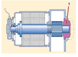
For the other principal type of traction motor, the bearing unit for the drive side is situated in the gearbox (fig. 7). The unit is based on a flanged design and supports radial and axial loads. This bearing is oil lubricated and suitable for higher-speed operations.
For the opposite non drive side bearings, radial load is lower and these can be built with relatively smaller dimensions. Normally these bearings have grease lubrication to allow reasonably long lubrication intervals.
In this case the user benefits through the reduction in components and space requirements. This design is suitable for compact gearboxes and allows for higher speeds and increased radial and axial loads. Overall life-cycle cost is reduced, and there is the advantage of dealing with a single system supplier.
Gottfried Kure,
SKF Railway Marketing,
Steyr, Austria


