E-Truck revolutionises the future of industrial vehicles
SKF IDENTIFIES CUSTOMER REQUIREMENTS
Summary
The E-Truck signals the arrival of a new era in industrial vehicle technology. It demonstrates the potential of electromechanical control systems and sophisticated electronics in applications ranging from forklift trucks to agricultural machines such as harvesters and tractors to mining and construction equipment. By successfully merging mechanical and electronic technologies, SKF has proven its ability to develop solutions to meet OEM needs for improved reliability, increased operator efficiency, reduced maintenance and energy efficiency. Also, by eliminating hydraulics, downsizing sub-assemblies and decreasing energy consumption, SKF technology has the potential to reduce the burden on the environment.
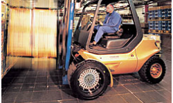
Combine hydraulic-free operation with highly sophisticated mechanical and electronic components, package them in a concept forklift, and you’ve got the E-Truck, SKF’s vision for the future of the industrial vehicle market.Using highly reliable electric systems to eliminate hydraulics, reduce energy consumption and decrease dependence on fossil fuels, SKF’s E-Truck demonstrates the kind of efficiencies that can be achieved through the integration of mechanical and electronic technologies.
SKF designed the E-Truck as a concept vehicle, to show the world that SKF’s capabilities go far beyond the design and manufacture of high-quality bearings and related products. The E-Truck represents the group’s vision and commitment to developing and providing solutions for industrial vehicles. The goal is to present these concepts today, and develop products with partners based on the interest generated by the E-Truck. The SKF systems on the E-Truck have applications well beyond forklift trucks. They can be used in agriculture, forestry, marine, mining and construction equipment and a variety of other applications.
Concept based on customer input
The E-Truck concept is based largely on input from customers gained over the past two and a half years. Discussions with customers, suppliers and end users have identified their needs in terms of functionality and performance. While some issues are common to all, the main issue for original equipment manufacturers (OEMs) is that of increased profitability.
More specifically, OEMs want to develop products that increase the productivity and efficiency of the end user in order to differentiate their products in the marketplace. In addition, they want to develop products that are reliable and simple to maintain in order to reduce warranty costs. They also want environmentally friendly products – OEMs are concerned about reducing the end-user exposure to hydraulic leaks or the exhausts of internal combustion engines and want safer products that will reduce their liability. Finally, the SKF industrial vehicles team found that OEMs want reduced part counts and simplified assembly procedures in order to reduce manufacturing costs.
Addressing customer needs
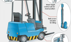
With the E-Truck concept, SKF engineers addressed all of these issues. To start, they took a forklift truck and stripped it down to the frame. All of the existing systems were removed and the vehicle was rebuilt, using an electromechanical steering system, actuators for lifting, tilting and side shifting, mast height control and direct-drive traction motors.
Electromechanical steering system
Combining intelligent sensor technology with the simplicity of “plug-and-play” packaging, the SKF electromechanical steering system is a closed loop operation:
- The operator turns the wheel and a signal is sent to the controller.
- The controller receives the input signal and sends a command to the actuator.
- The actuator steers the wheels.
- A sensor in the kingpin measures the position of the steered wheels.
- A feedback signal sent to the controller corrects any discrepancies.
Intelligent sensors improve ergonomics
Sensors detect the E-Truck’s steering requirement and supply a steering-angle set-point signal to the electronic control unit. This unit calculates the necessary actuator travel for the wheels to be turned and actuates the wheels accordingly. This steering concept eliminates the need for a steering column. The omission of the steering column means that there is no mechanical connection to the wheels to be steered. This opens the door to new ideas regarding the shape, position and location of the steering mechanisms. The cabin can be designed with the steering situated in non-traditional locations, and it can be programmed for maximum comfort and driver efficiency. It allows for more freedom of layout to optimise the ergonomics. In addition, the driver’s legroom is not restricted. This dramatically improves the comfort, safety and efficiency of the operator and simplifies design constraints and assembly procedures for the OEM.
Designed to be fail safe, the steering system has redundant components in the steering input device, feedback sensors and microcomputers. If one component fails, another continues to work so that the operator can drive the vehicle at a reduced speed to a safe location to await repair.
Reduced environmental impact
Replacing traditional hydraulic steering reduces maintenance and the impact on the environment because potentially harmful hydraulic fluids are eliminated. No hydraulics in the operator cabin means the driver no longer has to worry about high-pressure leaks and, because electromechanical steering is quieter, there is less noise in the cabin, which increases operator comfort and, ultimately, efficiency.
Programmable steering sensitivity and feedback
The ability to program sensitivity and feedback is a key component of the electromechanical steering system, which provides a great deal of flexibility. The system can be programmed so that the steering wheel turns two times lock-to-lock, or six turns; the adjustability is almost limitless. The system can also allow for steering sensitivity changes with vehicle speed. The speed/sensitivity feature makes it easier for the driver, especially in tight turning situations. When a driver is driving slowly and wants to turn, he doesn’t have to move the steering wheel as much as when he is driving faster, for example. In off-road vehicles, it is often necessary to steer the vehicle quickly at low speeds and slowly at higher speeds. This can be programmed into the SKF software used in the system.
Steering system components
The steering system consists of four components: a mechanical/electronic (mechatronic) steering device, a controller, kingpin sensors integrated into the axle and a steering actuator. Each component “talks” to the next, using Control Area Network (CAN-bus) protocols. Steering is a safety-critical function and using the open bus protocol communication can be critical when there are other users on the same CAN-bus. For this reason, the sensors and actuators in the SKF system are interfaced separately to the controller. Time-triggered protocol may alleviate these issues, but industry has not yet adopted this protocol.
Steering device
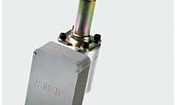
The steering device includes rotary sensors, an electromagnetic brake and a microcomputer. These components are integrated into the housing of the steering device to provide protection from harsh operating environments. The housing is simply mounted on the cabin dashboard or armrest. When the operator turns the steering wheel, the system’s sensors “sense” in which direction the driver has turned the wheel and how far.
Rotary sensor
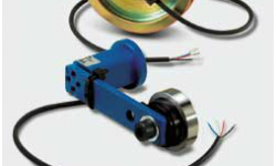
The rotary sensor uses non-contact, state-of-the-art technology that reduces susceptibility to wear, enabling the sensor to meet the durability and long-life expectations of both OEMs and end users. The rotary sensor is an absolute sensor that allows for alignment of the steering wheel knob to the position of the steered wheels by means of software. A sensor bearing used to support the steering wheel shaft provides redundancy in the steering device.
Electromagnetic brake
The electromagnetic brake in the steering input device is used for variable steering feel or force feedback and to simulate end stops. When used to simulate end stops, maximum current is applied to the brake when the steered wheels almost touch their end stops. The brake is released as soon as there is a steering movement in the opposite direction. Compared to other solutions for force feedback, such as DC motors, DC brushless motors or magneto-rheological fluid brakes, the electromagnetic brake offers lower power consumption, compact dimensions, excellent control properties and low cost.
Integrated controller regulates all steering functions
The steering sensor sends a series of signals to the controller, which in turn tells the steering actuator how far to actuate and in which direction. It is this integrated controller that regulates all steering functions. The system software prevents a delay in steering response when the driver turns the steering wheel in the opposite direction or stops turning the wheel. When the driver turns the steering wheel in the opposite direction or stops turning the steering wheel, the desired angle is set to the actual angle by software to prevent a delay in steering.
Kingpin sensors provide feedback
A kingpin sensor, integrated into the main axle, measures the position of the steered wheels. This sensor provides feedback, which is sent to the controller for comparison against the desired position input so that any discrepancies can be corrected. The system uses state-of-the-art non- contact absolute position sensors with high resolution for the desired steering position input and feedback. The sensors are fully integrated into the system and are protected from harsh environmental conditions typically encountered with industrial vehicles.
Mast height control unit
The E-Truck is also equipped with a mast height control unit that facilitates the automatic positioning of the mast. To ensure that the mast stops at the correct heights for different shelves or other storage devices, the output from the mast height control unit can be used as an input to the vehicle’s controller to identify pre-programmed locations automatically. By simply pushing a button or flipping a switch, the mast can automatically position itself to the desired height. The forks on the truck will reach their desired height as efficiently as possible, no matter who is operating the vehicle. It takes the guesswork out of the process and allows operators to work at maximum efficiency, resulting in increased productivity. To provide additional safety, the speed of the vehicle can be limited, based on the height of the mast, reducing the possibility of a vehicle tipping over.
Bearing integrated with sensor electronics
The mast height control unit integrates a bearing with sensor electronics to detect the height, speed and acceleration of the mast. It is mounted on the mast so that it can monitor its location as it travels up or down. As the mast is raised and lowered, the control unit sends a continuous signal to the controller. These signals are interpreted into precise measurements and can be displayed on a digital readout. With either a pre-programmed mast height system or a simple digital readout system, the vehicle “knows” the height of the load and can trigger other safety systems. For example, the safety system can be programmed to limit speed or turning radius depending on the height of the load. This reduces the possibility of the vehicle tipping over.
Alternatively, the safety system can be set to prevent the mast from rising beyond a specified height when the load exceeds a predetermined weight.
In addition to this application, sensor bearing technology can be used in any type of application where position, speed and acceleration are key operational parameters. This can include anything from an electric motor to the wheels in a high-speed train.
Mast
In the E-Truck, the hydraulic cylinders, normally used to lift and tilt the mast and to move the fork carrier from side to side, were replaced by highly efficient and extremely accurate actuators – ball screw actuators for lifting and roller screw actuators for tilting and side shifting. These actuators must work precisely or the mast will jam as it raises and lowers. As they are so efficient, they use a minimum amount of energy to raise a load – and return a maximum amount of energy to the batteries when the actuators are lowered. Due to the high quality and efficiency of these actuators, and the fact that they are maintenance-free, end users will actually save money over the life of the vehicle. Replacing hydraulics with actuators means quieter operation, the elimination of environmentally damaging hydraulic fluid and improved field of vision through the elimination of hydraulic hoses.
The actuator is driven by an electric motor, with the power transmitted to the screw through a worm gear.
Wheel
Though not an SKF design, the wheel is an essential element of the E-Truck concept. The self-propelled design affords a number of possibilities in terms of space, weight and energy savings. The wheel features a direct-drive electric motor that eliminates the need for a gearbox and increases the efficiency of the vehicle while simplifying the design. For example, a gearbox and its linkage to the wheels represents friction and weight and also increases the vehicle’s complexity, which results in increased maintenance. The wheel has advanced electronic controls that match the power setting of each of the wheels leading to greater efficiency and eliminating wear and tear on the tyres. Motion sensors provide the exact energy requirement to each wheel – moving the power to the wheels that grip and removing it from the wheels that slip.
Conclusion
Overall, the E-truck design demonstrates the power of combining electromechanical controls with sophisticated electronics. In creating such a concept vehicle, SKF also proves its own abilities in helping its customers develop solutions that address their requirements for future industrial vehicle design.
SKF IDENTIFIES CUSTOMER REQUIREMENTS
SKF conducted an in-depth analysis of OEMs and end users to gain a better understanding of their needs. The following requirements were identified:
End stops of steered wheels should be simulated so the driver knows when to stop turning the steering wheel.
The sensor solution used in the steering wheel and steered wheels must be a robust solution, capable of surviving in harsh off-road environments.
The complete system should provide the maximum safety for the driver and meet all applicable safety standards.
Steering functions should be programmable, making it possible to program the number of steering wheel turns lock-to-lock, steering feel, steering sensitivity and so on.
The force feedback in the steering device should be variable. For example, there could be low force feedback at low vehicle speeds and more force feedback at higher vehicle speeds.
SKF E-TRUCK
Carry capacity: 3.5 tonnes
Lifting height: 3.25 m
Lifting speed: 0.45 m/s
Two-wheel motor (brushless DC): 7.5 kW
D = 536 mm
B = 345 mm
Max torque: 3,000 Nm
Efficiency: 91 %
Seven electro actuators
Two lifting actuators
Two tilt actuators
One side-shift actuator
One steering actuator
One cabin actuator
Susan Langer
Global Program Manager, Industrial Vehicle Systems, SKF Industrial Division


