Grease life in lubricated-for-life deep groove ball bearings
Advanced grease-life estimates for lubricated-for-life ball bearings can be made with a new diagram that includes operating temperature and grease type.
In many grease-lubricated bearing applications, the service life of the grease exceeds the bearing life, so that no grease needs to be added during the bearing life. For such applications SKF provides ready-greased bearings and bearing units with integral seals or shields, which are suitable for maintenance-free operation.
In order to judge if a maintenance-free solution is possible, the grease service life is estimated from operating parameters. The main factors that determine the grease service life are bearing type and size, speed, operating temperature, grease type and the bearing environment.
In principle, the new relubrication interval diagram that is published in the new SKF General Catalogue 5000 can also be used to estimate grease life in lubricated-for-life bearings, but the outcome may be conservative. The calculation rules and corresponding limitations specified in the “Lubrication” section in the SKF General Catalogue are primarily focusing on applications with relubricated bearings.
More detailed calculations that would be desirable for lubricated-for-life bearings – for example, calculations exceeding 30,000 hours and usage of special greases and unusual operating temperatures – are not covered there. For advanced grease-life calculations for lubricated-for-life bearings, SKF has developed a new tool, which is further explained in this article.
Grease-life factors
Current grease-life calculation tools are mainly based on empirical models. Parameters such as bearing type, bearing size, speed and operating temperature are generally accepted as primary parameters.
Existing diagrams show all sorts of distortions, which are apparently caused by insufficient separation between normal and exceptional data points used for the curve fitting. By further analysis of available field data and by running many grease-life tests in the laboratories, SKF engineers have managed to better understand grease-life phenomena and to improve existing models.
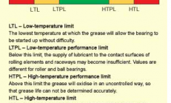
An important step was made by recognising different grease failures as a function of operating temperature. This understanding resulted in the formulation of the SKF “traffic light” concept, which is published now in the SKF General Catalogue 5000. This concept is summarised in ure 1.
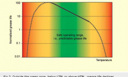
With the identification of the low-temperature performance limit (LTPL) and the high-temperature performance limit (HTPL), a temperature range can be defined where grease will function reliably and grease life can be determined accurately: the green zone. For this green zone more neat correlations could be derived for the primary parameters, resulting in a type of Arrhenius equation, which is typical for a chemical reaction rate as a function of temperature.
ure 2shows schematically the predictable behaviour of the grease life in the green zone. Bearing applications running outside the green zone must be treated as exceptions, as grease-failure mechanisms are abnormal (more complex, with a large spread) and more difficult to predict.
Also for the speed parameter A = n x dm, where n is the rotational speed in r/min and dm is the bearing mean diameter in mm, existing grease-life data have been rearranged. Above a particular speed, conventional greases tend to fail in an early stage, whereas modern, specifically designed greases can have a normal failure mechanism up to much higher speeds. Restrictions on speeds should not lead to distortion of curves in a general model, but must be defined per individual grease.
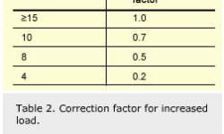
Finally, the effect of load on grease life was introduced as a separate correction factor. At low loads (i.e., C/P≥ 15) grease life is independent of the load, but for higher loads (C/P <15), a correction factor is required. In some older models, larger bearings were apparently treated more conservatively, as these were often involved in applications with relatively high loads.
The above analysis has resulted in the new relubrication interval diagram in the SKF General Catalogue 5000, which is valid for an operating temperature of 70°C, using good quality lithium thickener/mineral oil greases. Recommendations on how to account for the accelerated ageing of the grease with increasing temperatures and related limitations are given separately. The equations behind this relubrication interval diagram are also used for the development of the dedicated diagram for lubricated-for-life bearings.
Lubricated for life
Recommendations for grease life are always based on statistical rules. The SKF relubrication intervals are defined as the time period at the end of which 99% of the bearings are still reliably lubricated. This represents the L01 grease life. For lubricated-for-life bearings, the grease life is preferably defined as L10, which is in line with definitions for bearing fatigue life. For a typical grease life distribution, the correlation between L01 and L10 is L10 ≈ 2.7 L01.
For relubrication, intervals in excess of 30,000 hours (~3½ years) are not advised, but there is no reason to maintain this limit for grease-life estimates for lubricated-for-life bearings. In real life, many pre-greased and sealed bearings in simple applications run much longer than predicted with the existing tools. As there is more certainty for lubricated-for-life ball bearings, which are filled in the SKF factories with a grease of known quality with proper cleanliness and an optimal fill quantity, it is justified to have an extended tool for grease-life calculations for such bearings.
A first step towards an improved grease-life calculation tool was already made for SKF Y-bearings, with a new diagram pub-lished in Evolution 3/03. In the next section a more universal diagram is presented for a wider speed range and with extra features.
New diagram
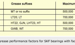
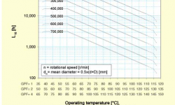
A new sophisticated diagram ( diagram 1) was developed for lubricated-for-life deep groove ball bearings using the same model as for the relubrication diagram. In this diagram, grease life L10 can directly be read as a function of the speed parameter A, operating temperature and grease type. Differentiation between greases is achieved with a grease performance factor (GPF). For three different GPF values (GPF= 1, 2 or 4, respectively), there is a different horizontal temperature scale in the diagram. In table 1 GPF values are specified for factory-fill greases applied by SKF, together with speed limitations for the life calculation for each of the greases.
The adjustment for temperature is the same procedure as explained in the SKF General Catalogue for the relubrication interval. In the shape of the curves, one can recognise the interval where the grease ageing follows the rule of a factor of 2 for every 15°C increase (inclined part) and a horizontal part at the lower temperature range. The solid parts of the curves are in the green zone, delimited by the LTPL and the HTPL.
The diagram nicely assists in choosing grease with optimum GPF value. The following examples show that a higher GPF is not always an improvement.
In a sealed deep groove ball bearing operating at
n x dm=300,000 and 55°C, a grease with GPF=1 is the best solution, giving L10=30,000 hours. For GPF=2 the estimated life is the same, whereas a grease with GPF=4 is not recommended, due to a shorter life.
In a shielded 6302-2Z deep groove ball bearing operating at 15,000 rpm (A=428,000), at C/P=8 and 90 °C, the L10 is estimated at 1,500 hours for a grease with GPF=1 (including a correction factor of 0.5 for the load ( table 2). A grease with GPF=2 would give a grease life L10 ≈3,000 hours. However, there is only partial advantage for this increase, as the estimate for the bearing fatigue life under these conditions is L10 ≈ 2,100 hours (calculated with the SKF rating-life method). Application of a grease with higher GPF is often more expensive, so the extra costs must be justified.
The visualisation of the effect of temperature on grease life in the new diagram is very useful when designing a bearing application. In case the grease life is the bottleneck for the life of the system due to internal heat generation, it is worthwhile to consider design improvements, focusing on better heat transfer and lower bearing operating temperature. Selection of a grease with higher GPF value can then be avoided, if feasible, which can have a positive effect on costs.
Correction factors
Outside the green zone, below LTPL or above HTPL (represented by the dotted lines in .2 and diagram 1) the grease life declines relatively rapidly, caused by deviating failure mechanisms. In these ranges it is not possible to predict grease life accurately on the basis of the general model.
The value estimated from the diagram is the minimum grease life (L10) that can be attained in SKF lubricated-for-life deep groove ball bearings running under optimal operating conditions with inner-ring rotation at low loads. This base line is representative for bearings with steel cages and metal shields (2Z bearings). For special bearing executions it is possible to achieve longer life under certain conditions, for example with special cages, advanced sealing systems (2RS1, 2RSL, 2RZ, etc.), ceramic components, etc. For more details, please consult the SKF application engineering service. The diagram can also be used as a baseline for other sealed radial ball bearing types, such as angular contact ball bearings and self-aligning ball bearings.
At increased loads (C/P. For additional adverse operating conditions, such as vertical shafts, vibrations, etc., correction factors are specified in the “Lubrication” section in the SKF General Catalogue. Life calculations for exotic greases (e.g., with silicone or fluorinated ingredients) can not be made with the new diagrams, as the ageing for such greases follows different rules.
The grease life calculations in the interactive tool LubeSelect (www.aptitudexchange.com, see also Evolution 4/01) now follow the same rules as in the new SKF diagrams described here. The validity of the new diagram and the GPF values for the standard greases listed in table 1 have been confirmed through extensive grease-life testing in the SKF R0F rigs at the SKF Engineering & Research Centre in Nieuwegein, the Netherlands.


