The SKF high-capacity cylindrical roller bearing
The ISO definition of a full complement bearing states that the bearing does not have a cage. When that definition was written, it was not technically possible to have a full complement bearing with a cage. But times have changed, and SKF has once again rewritten the book of possibilities.
The ISO definition of a full complement bearing states that the bearing does not have a cage. When that definition was written, it was not technically possible to have a full complement bearing with a cage. But times have changed, and SKF has once again rewritten the book of possibilities.
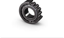
As SKF celebrates its 100th birthday, the spirit of innovation that started the company is still with us. Today, as in 1907, scientists and engineers throughout the company are continually working to optimize rolling bearing life and improve machine reliability. One of the most recent examples of this innovative spirit can be seen in the new SKF high-capacity cylindrical roller bearing. The unique feature of this bearing is that SKF engineers have been able to increase bearing load-carrying capacity substantially while maintaining its standard boundary dimensions. In other words, they created a bearing that combines a load-carrying capacity comparable to a full complement bearing with the benefits of a bearing with a cage (fig.1).
In 1960, when SKF introduced the E-design cylindrical roller bearing, it was seen as an important step in the development of standard cylindrical roller bearings. The bearing was based on standardized boundary dimensions; it was the internal macro geometry that set it apart from the rest. SKF engineers had found a way to optimize the number of rollers, the roller size and the thickness of the inner and outer rings, leading to an increased load-carrying capacity and rated bearing life. But research did not stop there. In the 1980s SKF engineers went on to develop the EC design, which had a higher thrust load-carrying capacity, and then the SKF Explorer cylindrical roller bearings, which were launched in 2002. The SKF Explorer bearings benefited from improved material and an improved heat-treatment process, but it was mainly the improved micro geometry that put these bearings above the competition. Using knowledge gained over the years, together with proprietary software, engineers were able to maximize the effects of the lubricant film build-up and decrease the friction within the bearing.
About load-carrying capacity
Load-carrying capacity is calculated using standard ISO 76 and ISO 281 formulae. According to these formulae, there are two ways to increase the load-carrying capacity of a bearing while maintaining standardized boundary dimensions:
-
Increase the dimensions of the rollers and maintain the same number of rollers; or
-
Increase the number of rollers and maintain the roller dimensions.
From a practical point of view, the first method leads to a technical problem. Increasing the size of the rollers will reduce the thickness of the inner and outer rings and the width of the side flanges. This has no effect on the theoretical load-carrying capacity calculation. In reality, however, these changes will reduce ring stiffness and flange strength. For the end user, this means a higher risk of micro movements in the bearing seating, which causes fretting corrosion or ring creep. Larger rollers also increase the risk of smearing damage, due to their higher moment of inertia.
All in all, the first method, though impressive on paper, cannot be considered an improvement. The second alternative, however, does offer viable alternatives. Based on the former improvements of the macro and micro geometries, the roller dimensions and wall thickness of the bearing rings can remain unchanged, compared with the dimensions of the proven 45-year-old E-design.
However, increasing the number of rollers within a defined envelope is not as easy as it sounds. To make this new bearing a reality, SKF engineers and scientists needed to work through a number of key issues.
“Add more rollers” – easy to say, hard to do
There are two types of bearings: caged bearings and full complement bearings. Full complement bearings, which do not use a cage, are fitted with a maximum number of rollers. In this type of bearing, the rollers are in direct contact with each other, which causes sliding and increases friction and heat generation. Under certain circumstances, this leads to wear and premature bearing failure, making them unacceptable for applications where there are higher speeds. This makes a cage essential for higher-speed applications.
Medium- and large-size cylindrical roller bearings are equipped as standard with a machined brass cage, mainly to keep the rollers from making contact. The cage bars, which usually are orientated around the roller pitch circle (the connecting circle of the mid-points of all rollers), have a defined cross section designed for maximum strength, but they reduce the number of rollers theoretically possible. However, by moving the cage bars away from the roller pitch circle, the rollers can be placed closer to each other so that more rollers can be incorpor-ated into the bearing. To do this, SKF developed a new window-type steel cage.
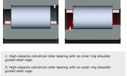
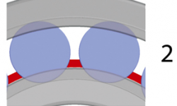
This resulted in two basic cage designs – an outer ring shoulder guided cage (JA) and an inner ring shoulder guided cage (JB) (fig.2).
More than cage bars
Larger window-type steel cages are not new. Cage diameters up to 1,300 mm have been used in large-size tapered roller bearings for years, with excellent results. The development was based on the same material thickness as a comparable tapered roller bearing cage, using a shoulder guidance of the cage to provide better performance for occurring radial accelerations and shocks. But the development team was faced with a number of issues. First and probably most important was how to maximize cage strength while enhancing the formation of a lubricant film. The team also needed to find a way to min-imize stress concentrations in the transition between the cage bars and side rings.
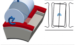
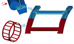
Using proprietary SKF software and knowledge gained from years of experience, the team determined that it could minimize stress concentrations in critical areas by smoothing transitions, increasing radii, optimizing wall thickness ratios and creating proper undercuts (fig.3). The team then went a step further to provide pure tangen- tial contacts between the rollers and cage bars. The contact angles were optimized, and the cage bar was designed with a slightly waisted shape (fig.4).This reduces contact pressures and enhances lubricant film build-up, but it also avoids edge contacts and thus localized dry running because of the scraping off of the lubricant. These design features have been proven theoretically as well as in practice, and a patent application has been filed.
In combination with steel as a cage material and shoulder support, the new features lead to strength that is comparable to standard brass cage executions. Even more remarkable, this is in spite of an increased number of rollers.
In addition to the development of the new cage design, high-capacity cylindrical roller bearings have, by default, black oxidized rollers and bearing rings to improve the run-in behaviour of the bearing. This surface treatment gives the bearing its dark colour (fig.1).
Once theoretical calculations and simulations were completed, the new cage design was tested for more than a year. During this time, more than 20 validation tests were conducted. The tests, which used 2334 size cylindrical roller bearings, were designed to compare the performance of both high-capacity cage variants with a standard shoulder guided, machined brass cage.
Speed and functional tests
To assess speed capability and cage stability, n x dm values (rotational speed x bearing mean diameter) of up to 800,000 mm/min were applied under alternating radial and axial loads. The applied speed corresponds to the limiting speed of the catalogue bearing.
The tests were conducted under two different lubrication conditions. In one case, oil with a proper viscosity to provide a sufficient oil film ϰ > 1.5) was used. In the other case, a low-viscosity oil to simulate an inadequate lubrication condition ϰ < 0.5) was used. When all the tests were completed, a 1,000-hour duration test was conducted. During the tests, all critical performance parameters such as temperatures, loads, speed and vibration levels were monitored continuously.
Results
Based on the results of the measurements, together with an in-depth examination of the various bearing components after the test, no restrictions could be found to the SKF high-capacity cylindrical roller bearing usage limits, compared with the standard bearing.
When compared with a machined brass cage, the reduced cage cross section of the high-capacity cage improves oil flow through the bearing to maximize the effects of the lubricant and reduce heat generated by the bearing. Another advantage of the high-capacity cage is that its lower weight reduces inertial forces. This can be particularly important in applications where there are frequent fast starts and stops and in applications subjected to radial acceler-ations, such as planet wheels.
Low-load tests
In addition to high-speed and cage stability tests, the bearings were also tested under minimum load conditions to investigate the risk of roller slip, smearing and other damage that typically reduces bearing service life. The minimum load tests were conducted with less than 10 % of the recommended minimum load as prescribed in the SKF General Catalogue.
Results
The results of the test showed that, in particular, the inner ring shoulder guided JB cage reduced the slip ratio by up to 50 %, when compared with a bearing with a standard brass cage.
The wind turbines impact rolling bearing technology
The need to increase power density and reliability, particularly in wind turbines, has driven a number of developments in the bearing, seal, lubrication and condition monitoring industries. From a bearing standpoint, high-capacity cylindrical roller bearings have found their application here. They are mainly developed for cylindrical roller bearings in the 22 and 23 heavy series, from medium to large sizes (bore diameter from 150 mm up to approximately 300 mm). Other sizes can be manufactured on request. Depending on the cage variant, bearings in the 23 series can have up to two extra rollers; bearings in the 22 series can have up to three or more rollers, when compared with a standard bearing of the same size. It is notable that the JA cage variant for bearings in the 23 series has as many rollers as the full complement version, so it has reached the upper limit of load-carrying capacity. In this case, one can indeed speak of a full complement bearing with a cage.
For a wind turbine, this increased load-carrying capacity provides an opportunity to downsize or increase power density. Either way, it is an important development for an application that is perched atop a pedestal 90 metres in the air.
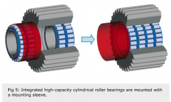
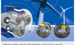
Due to the strong over or under roller pitch diameter cage design, the retaining of the rollers by the cage is not possible and the rings of the high-capacity cylindrical roller bearings cannot be mounted separately. In some applications, such as the planetary wheels of wind gearboxes, the raceway of the outer ring is integrated into the bore of the planetary wheel. Since a bearing outer ring is not necessary for this solution, the bearing will be delivered with a sleeve that can be used for mounting the bearing (fig. 5).
The planetary gearboxes in smaller wind turbines that were built in the past often used full complement cylindrical roller bearings in the planets. These bearings, which have a high load-carrying capacity, typically generate more friction than a caged bearing, due to direct roller-to-roller contact. In smaller gearboxes, these bearings seem to work satisfactorily. However as wind turbines have become larger, there is an ever-increasing risk that these bearings will fail prematurely, due to smearing and wear.
Comparison of different bearing designs
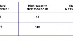
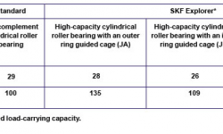
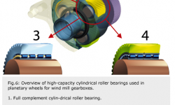
In fig. 6various bearing designs are compared, using a wind turbine gearbox as an example. As you can see, standard cylindrical roller bearings with a brass cage have a lower calculated life than full complement roller bearings in the planetary drive unit. If you compare a full complement bearing to SKF’s new high-capacity cylindrical roller bearing, the gap narrows. And when the high-capacity bearing is manufactured to the SKF Explorer performance class, the rated life of the bearing exceeds the life of a full complement bearing.
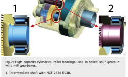
This is not a unique example. Similar results can be seen in the intermediate and output shafts of a spur gear transmission. In this type of transmission, a full complement bearing cannot be used, due to the higher speeds. In addition, the bearing typically does not have the required minimum load applied to it. As a result, when comparing the calculated bearing life of the standard caged bearing with the life of a similarly sized high-capacity bearing (fig. 7),there is the possibility of increasing bearing life by up to 35 %. The inner ring guided cage variant is recommended in this application because of its resistance to smearing.


