Improved lubrication in paper machines
A joint study between Safematic, part of SKF, and the Tampere University of Technology in Finland has led to an improved lubrication solution that meets the demands and the extreme lubrication conditions in the pulp and paper industry.
A joint study between Safematic, part of SKF, and the Tampere University of Technology in Finland has led to an improved lubrication solution that meets the demands and the extreme lubrication conditions in the pulp and paper industry.
Safematic,founded in Finland in 1972, has made its name as a lubrication specialist for the pulp and paper industry, involved in lubrication automation and mechanical sealing. In August 2006, Safematic’s lubrication business was taken over by SKF and since then, together with VOGEL, it has been a part of SKF’s lubrication platform. Jointly, VOGEL and Safematic form a global and comprehensive supplier of automated lubrication systems for all industries.
Nordic countries are major paper makers
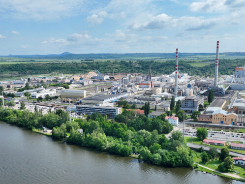
Safematic, as part of SKF Finland, acts as the centre of excellence for lubrication automation in the pulp and paper industry and is also responsible for lubrication automation solutions for cement and mining industries. The factory is located in Muurame, about 250 km north of Helsinki (fig. 1), where 120 employees take care of manufacturing, engineering and full customer service around the globe.
As the Nordic countries have strong pulp and paper industries, Safematic products have evolved to give significant benefits in the lubrication products the company offers to this industry. For example, Safematic has more than 500 modular stainless steel grease distributors for reliable lubrication solutions in paper machine wet end applications, some of which have been operating for more than 20 years.
However, today the biggest challenges are in the lubrication of modern, high speed paper machines.
Paper machine lubrication
With lubrication literally acting as the lifeblood of today’s paper-making processes, paper producers increasingly use oil circulation lubrication systems both in the drying sections and other heavily loaded, hot parts of the process. In addition to traditional oil-lubricated drying cylinder bearings, many of today’s machines have oil lubricated felt rolls and gear reducers for the drying sections and the wire and press section rolls. They also run at faster operating speeds and higher temperatures, which increase the demands for lubrication.
Yet despite these increased lubrication requirements, the basic construction of lubrication systems has remained the same. While some significant developments have occurred in oil filtration over recent years, effective technical solutions need to be found in some areas.
These include:
-
Water and humidity problems caused by the higher operating temperatures of the drying sections and the oil lubrication of the wire and press sections in modern paper machines.
-
The increased turbulence, caused by greater oil flow through the bearings, which creates extra bubbles in the oil and decreases both the efficiency of the lubrication and the service life of the oil.
-
The increasing size of the oil tanks, which provides the higher oil flows and pumping capacities necessary to ensure efficient lubrication and cooling, creates higher operating costs, more environmental issues and a greater risk of
problems arising from the use of inflammable liquids.
With these problems in mind, a joint project between Safematic and Tampere University of Technology was launched to simulate and study the real characteristics of oil flow in lubrication systems. The project results cast a whole new light on oil circulation and the new generation of equipment, resulting in the fact that it is now already in use at over 100 international locations.
The aims of the study
The principal aim of the study was to deve-lop a lubrication system that would solve the main problems affecting existing lubrication systems, with specific attention being paid to:
-
More efficient use of the oil
-
Removing water from the oil
-
Removing foam and air from the oil
-
Reducing energy and cooling water consumption.
The first stage of the study analyzed exactly how traditional oil tanks operate, and this information was used to develop a more efficient construction model which would improve the identified problem areas.
How efficient are traditional oil tanks?
The dimensions of traditional rectangular oil tanks (fig. 2) were based on a 30-minute retention time, assuming that the oil moves smoothly from the return inlet to the pumping area, with the flow being controlled by intermediate walls of the tank.
To test this theory, a computer simulation based on particle vectors (Fluent 3D) was created and tested. Surprisingly, the survey clearly showed that only 30–50 % of the oil circulates in this way, with the rest either moving very slowly or simply remaining static in the tank (fig. 2).
The picture below shows a return inlet on the left end of the tank, with the red and white colours indicating relatively fast-moving oil underneath it. A certain quantity of oil is flowing directly at high speed across the control walls to the suction side of the tank on the right hand side, and then direct to the suction outlet.
This diagram shows only one cross-section of oil flow in the centre of the tank. Other cross-sections towards the sides of the tank would show more areas of blue, indicating lower oil flow speeds. These results show clearly that the efficiency of the oil circulation in a traditional tank is very poor, because not all the oil is actually flowing, the real retention time is actually only between 5 and 10 minutes, instead of the supposed 30 minutes.
The problem of water contained in oil
Many problems of water contained in oil in existing paper machines are caused either by the formation of condensation in return lines or leakage in the cylinder steam joints. Bearing manufacturers usually recommended a maximum water content for the oil of 200 ppm (0.02 %). However, in reality the percentage is often several times greater than this, and in extreme cases even higher. Modern high-speed machines are especially prone to these water problems because of the greater temperature changes in their return lines and due to the fact that oil lubrication replaces grease in the wire and press sections.
The water, either in microscopic drops or mixed in with the oil, dramatically reduces lubrication efficiency by breaking the oil film that separates the bearing rolling elements and raceways. The heavier the bearing loads, the more damaging this will be.
Water also reduces the service life of the oil by changing the chemical properties of additives such as corrosion resistant and EP-additives – a problem which is exacerbated by high temperatures.
The actions of foam and air in the oil
Foam and air in the oil always cause lubrication problems as the microscopic air bubbles break the oil film that separates the bearing rolling elements and raceways, thus shortening the bearing service life. Air also increases the oxidation of the oil, deteriorating its chemical and physical properties and shortens the service life of the oil. In addition, problems caused by air in an oil circulation system will increase greatly if a clogged or incorrect return filter is used.
Reducing energy consumtion
In traditional pumping units, pressure regulation is controlled by a separate pressure valve that requires a certain overflow of the oil to maintain a steady pressure in the piping system. This means that normally, some 15–25 % of the pumping capacity is used just to maintain system pressure, and this represents an inefficient use of energy that continues 24 hours a day.
In addition, all the other system components must be sized according to this maximum oil flow – for example, cooling of the 15–25 % additional oil volume will use a tremendous amount of water in a year, and this is another significant waste of resources.
Better oil flow from a smaller tank
Based on the analysis of these problems and the way they relate to the traditional oil tank, a new design – known as the Flowline tank – has been developed by Safematic. Perhaps the Flowline’s most obvious feature is the radical circular footprint that replaces the traditional rectangular format. This new design enables more than 90 % of the oil to circulate in the lubrication system, and also significantly improves oil retention performance (figs. 3 and 4). This enables the total amount of oil in the system to be reduced by 30–50 %, which dramatically cuts the size of the tank needed as well as associated oil costs. The service life of the oil remains largely unaffected, and in some cases it is actually increased compared to a trad-itional lubrication system.
In certain special applications a rectangular shape tank design with a similar prin-ciple is used. This design was originally developed by VOGEL, and uses a package of corrugated plates (plate separator) in the oil tank. The construction combines good deaeration and dewatering and allows downsizing of the tank as well, especially in big systems with pumping capacities over 900 l/min.
The Flowline tank installed on paper machine No. 5 at the UPM Kymmene Oyj Tervasaari mill in Finland has already proven its worth in action. The mill’s Mechatronics Supervisor for Mechanical Maintenance Heikki Kataja says: “We switched to a Flowline lubrication system featuring the new tank design in 1998. The cellar of our building is rather low and narrow, so the reduction from the old 8 m3 tank to the 3 m3 Flowline tank was a major benefit, especially considering that the flow rates are equal in both tanks. The start-up went extremely well and we have had no real problems to date”.
Effective removal of both air and water
In the new Flowline tank, water removal has also been improved in two different ways (fig. 3): The tank features numerous intermediate horizontal plates that behave in a similar manner as the intermediate walls of a traditional tank, helping to regulate the flow of the returning oil on its way from the centre of the tank to the walls. Because the plates are placed close together, all small water droplets in the oil need only to sink a few centimetres before they meet the next plate which then directs them down to the tank’s central drain tube.
The new Flowline design removes water far more effectively than traditional tanks, and means that the oil only needs to be retained for a few minutes to separate out the majority of non-dissolved water drops. This increases the efficiency of water removal and helps to avoid water-related problems which would otherwise arise.
Water removal is another feature of the Flowline tank which has impressed UPM’s Heikki Kataja. “Under normal operating conditions the water content is very low – around 3.4 to 0.4 % measured on the Vaisala scale (oil saturation level). If under exceptional conditions water does get mixed with the oil, we can remove it quickly and easily. This takes one day with the Flowline tank, whereas it used to take up to a week with our previous tank. Also, the normal water separation system is so efficient that we only needed to use our separate removal system a few times.”
The Flowline tank design offers an additional benefit. As well as guiding water droplets downwards, the intermediate plates also separate the air bubbles and guide them upwards, creating a flow through the tank as shown in fig. 3.
Reducing energy and cooling water consumtion
The oil lubrication unit’s energy consumption can be reduced by using components with a higher efficiency ratio, such as screw pumps and plate heat exchangers rather than gear pumps and tube shell coolers. However, the biggest savings can be achieved by reducing unnecessary pumping capacity.
If the oil pressure of the system is regulated by adjusting the rotational speed of the pump by a frequency converter (vari-able speed AC drive), the pumping unit can always operate at its optimum energy consumption, providing exactly the amount of oil required by the lubrication points and
no more.
The Flowline system also helps to increase the service life of the oil, and this has been another significant aspect of the installation at Tervasaari.
Heikki Kataja confirms that the oil remains in good condition due to its low water content, and acknowledges that this has enabled the machine to run on a lengthy change interval of between 5 and 10 years. It also extended bearing service life and increased the runnability of the paper machine. The resulting economic benefits of this have prompted the Tervasaari mill to invest in an additional Flowline tank for the press section of their Paper Machine No. 6.
Advanced system control
Oil circulation systems have traditionally been controlled by a combination of manual monitoring and alarm-based automatic operations. Yet, as the size of the systems increased, the task of visual monitoring with manual controls became more and more complicated.
As a result, an accompanying range of Flowline system control equipment has been developed (fig. 5). As these are independent systems, they can be retrofitted to existing paper machines when the lubrication system is rebuilt. They are also very well suited for the use with a Flowline tank, and by connecting to the control mechan-isms of the paper machine itself they can provide a comprehensive range of facilities, which include:
-
Control and monitoring of system pressure.
-
Control and monitoring of system temperature.
-
Filter monitoring.
-
Oil level monitoring.
-
Oil flow monitoring at single lubrication points.
-
Temperature monitoring in different parts of the machine.
One key benefit of a Flowline control centre is the modern display technology that is used to provide maintenance engineers with the same versatile monitoring and control possibilities normally found only in a mill’s process control system. This helps to identify potential malfunctions quickly and efficiently and take preventive action.
A Flowline control system also allows full automatic start-up of the oil lubrication system. This avoids visual monitoring and manual adjustments normally needed to cold-start a lubrication system (particularly the larger ones) without cold, high-viscosity oil overflowing through the bearing housings. Automatic field control valves in the Flowline system allow the start-up procedure to be performed step by step.
")
")
")
")
")