Polymers enhance railway axlebox bearings
Historically cages used for railway axleboxes have been:
Significantly improved performance can be achieved through the use of polymer cages for roller bearings in railway axlebox applications.Optimised cage designs based on reinforced polymer material for cylindrical and taper roller bearings and units for railway axleboxes, have been introduced by SKF. The clear performance advantage of polymer cages is confirmed by friction coefficient, roller slip and operational temperature values.
Laboratory and field tests support the theoretical work on cage optimisation. The customer benefits of polymer cages are longer service life and improved reliability. SKF now selects the polymer cage as the standard for its roller bearings for these applications. In addition polymer cages are recognised by the main railway companies and OEM rolling stock suppliers.
Railway axlebox bearings are required to meet stringent demands of low maintenance, running reliability and safety. A key component in achieving these demands is the cage. Cages in rolling bearings fulfil many tasks. The principal one, however, is to ensure correct retention of the rolling elements during mounting and maintenance operations, thus allowing easier handling. During running, the rolling elements pass from the loaded into the unloaded zone where the cage has to guide the rolling elements. Further tasks for cages are to provide and distribute lubricant and to damp vibrations.
Historically cages used for railway axleboxes have been:
a) machined brass cages in a two-piece design with rivets or one-piece cages for cylindrical roller bearings; and
b) pressed steel cages for taper roller bearings and units such as tapered bearing units, TBU.
Today both bearing types are offered with a polymer cage.
Selecting the polymer
In general engineering applications, a polymer material is chosen for two important reasons. The first is its specific properties such as low weight and wear, high toughness and elasticity with an additional damping effect. The second is the moulding process, which allows the production of complex shapes that cannot be produced efficiently by traditional machining methods.
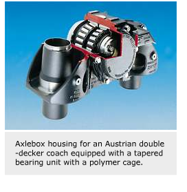
These factors also apply to cages for rolling bearings. Polymer cages have been used in bearings for general applications for more than 30 years with excellent results. The bearing producer has to consider the strength and elasticity over the whole operating temperature range, the higher thermal expansion coefficient and also the compatibility with lubricants and washing fluids. The design has to be suitable for the different operational functions inside the bearing, for proper high-quality moulding during production, for assembly and disassembly of rollers, taking into account the “roller drop” design feature. In railway axlebox applications, additional requirements for cages have to be considered, such as vibration and shock loads, reliability, safety and high efficiency (fig. 2).
Field parameters
The nominal radial and axial quasi-static forces in play during operation are well known. Different international standards also describe calculation principles to evaluate parameters such as rating life, etc. To calculate and simulate on test rigs the true dynamic behaviour based on realistic running conditions, SKF has taken field recordings on various characteristic main lines with different rail and wheel conditions in Europe, North America and Asia. Taking into account the worst wheel and rail conditions found in Europe, a basis for calculation and testing was defined that describes vibration, shock loading and temperature at different speed levels.
Calculation methods
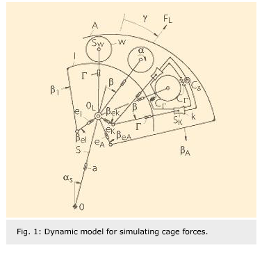
A two-dimensional calculation model from the Ruhr University in Bochum in Germany described a principal method for calculating cage forces. SKF developed this simulation method for bearings in railway applications to analyse the elastic behaviour of the cage under all types of vibrations and shocks, such as the influence of wheel flats and rail joints. The cage is modelled as an elastic structure where the cage mass is uniformly distributed over each mass centre of the cage bars (prongs) that are connected by means of the springs with radial, tangential and bending stiffness. The motion of each mass of rolling elements is described by a group of differential equations that are numerically solved in the simulation program (fig. 1). The results of these equations have been verified experimentally, based on operating conditions covering most practical situations.
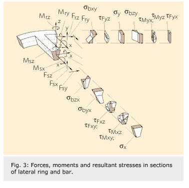
The inertia and support forces acting on the cage produce internal stresses. In the model of a cage cross section, the internal forces, F, and the moments, M, acting on the cross sections of the bars, s, and the lateral ring, r, are shown. The nominal value of the normal stress is calculated as a function of the longitudinal forces and bending moments, while the nominal value of shear stress is derived from the transverse forces and the torsional moments.
The stress components can be combined into an equivalent stress according to the form change energy hypothesis.
The change in direction of the force lines in the transition between the ring and bar increases their density and thus leads to stress peaks. The equivalent stress is obtained by multiplying the nominal stress values by a stress concentration factor. This factor can be calculated using the finite element method (FEM). It considers the cage pocket radius, cage ring and bar dimensions. This calculation model makes it possible to define accurately the forces acting on the cage and to optimise the design (fig.3).
Rig testing
At the SKF Engineering & Research Centre (ERC) in Nieuwegein in the Netherlands, several testing procedures were made to evaluate polymer cage performance for railway journal applications. These included tests with shaker rigs, dynamic testing and endurance testing. The SKF test rig for high-speed bearings (THISBE) is used to reproduce the dynamic load conditions encountered by a running vehicle of similar type or from a synthesised signal obtained from analytical simulation. Operating temperature is monitored throughout the test, after which all bearing components and grease are also examined to diagnose the bearing condition.
For endurance testing, the “R3” rig principle is used. This is a quasi-static testing method described in UIC 515-5 and also in the new European standard, EN12 082 (Evolution 3/1997, pages 24-27).
Of particular interest during testing is the bearing temperature. This is a tribological indicator for the complete bearing system. Low temperature indicates low friction. Low temperature is also beneficial to grease life, the maintenance intervals and the total life cycle cost. In comparison with earlier designs, the polymer cage has a lower and more stable running temperature, which confirms the expectations of the material properties.
Cylindrical roller bearings
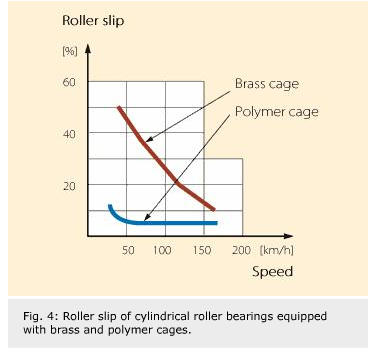
In cylindrical roller bearings, the roller slip depends on the speed and other parameters such as cage material and design. Leaving the loaded zone, the roller rotational speed decreases due to interaction with the cage bars. Entering the loaded zone, the roller must be reaccelerated rapidly which sometimes can cause smearing damage. If a shoulder guided polymer cage is used, the roller in the unloaded zone is free of cage guiding forces. This results in much less roller slip, so it provides a particular advantage in avoiding smearing damage. The test results show the clear benefits of the polymer cage material (fig. 4).
At lower speeds, in particular, roller slip is dramatically decreased.
The stabilised temperature after the running-in phase of axlebox bearings equipped with a polymer cage is around 15 °C lower than for a brass cage. This difference is maintained even when the speed increases. This test is based on the passenger-coach design for high-speed applications up to 200 km/h by the Chinese Railways. Today, large quantities of SKF bearings equipped with polymer cages are in operation.
Aside from the tests already mentioned, extreme conditions are also simulated such as running at high speeds of 330 km/h and endurance testing with a single grease fill, corresponding to a distance of 2.4 million km without relubrication.
One question sometimes asked by railway companies is, “How much time do we have to detect a hot running bearing?” This is strongly influenced by the cage type and design. To evaluate this, a lubrication shut-off test can be made to measure the time between the loss of lubrication and bearing failure. The brass cage can operate for a period without lubrication after which the bearing temperature increases considerably to reach the hot running condition that causes the bearing to seize.
The polymer cage can operate under the same conditions for much longer without any lubrication. After this period, the temperature increases, the cage bars melt and coat the rolling elements. This serves as an additional emergency lubricant. Even under such severe conditions (essentially without a cage), the bearing runs on for several hours as a full complement bearing without seizing. In those cases where infrared methods are used to detect hot boxes, bearings with a polymer cage allow much more time for railway operators to react.
The first field experience on railways with polymer cages in cylindrical roller bearings began in 1989 with freight wagons for Deutsche Bahn (DB). Today, all new German rolling stock, freight cars, passenger coaches and some new families of DB locomotives (types 101, 145 and 152) have polymer cages as standard for cylindrical roller bearings. Also other main European railway companies use the same bearing design with excellent results.
Tapered bearing units
For cages used in tapered bearing units, TBUs, a finite element model was prepared for the study of stresses and deformations in the interaction with the rollers. The results were checked against the material properties and were used to optimise the cage bar geometry and the transition to the lateral rings.
The maximum stress concentration is located in the area of the transition between bar and lateral ring. Calculated for the worst load condition, it is below 26 N/mm2. This is well below the material strength limit, which is a minimum of 40 N/mm2 after moulding.
When compared with pressed steel cages, lower friction and lower operating temperatures are the advantages of polymer cages. This results from the lower mass, lower sliding friction between the polymer cage material and the roller material and optimised pocket contact surfaces which are able to retain and distribute lubricant more effectively.
Extreme (high-speed) conditions were simulated by running at 330 km/h over 1.5 million km and at 400 km/h over 800,000 km without any relubrication. The operational temperature was stable and consistent around 60 °C (at 20 °C ambient temperature) over the period. After the test, no significant wear of the cage was detected, and the grease condition was not affected by steel contamination.
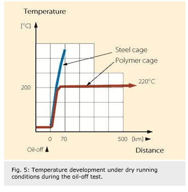
A further testing regime is the “oil-off test” that simulates a TBU running under defective conditions. The test starts with some oil lubrication feeding which is stopped after a conditioning period; the bearing is progressively starved of lubricant and eventually runs dry. The pressed steel cage failed after 70 km with a continuously increasing operating temperature up to the complete seizing of the bearing. Under the same conditions, the polymer cage can be operated at least five times longer than a pressed steel cage. The operating temperature of the TBU equipped with the polymer cage rose after a certain time up to 220 °C and was very stable. After about 500 km, the test was stopped (fig. 5).
The development of a polymer cage for a TBU began at SKF in 1982 with laboratory testing at the Engineering and Research Centre (ERC). The first TBUs equipped with polymer cages were delivered in 1990. Considerable experience of these cages in TBUs has been gained through their fitting on:
- Freight wagons transporting trucks via the Alps in Europe by railways in Austria, Germany, Italy and Switzerland.
- Coach types used by railways in Austria, Hungary, Italy and Switzerland with a maximum speed up to 200 km/h.
- High-speed trains such as the German ICE train family with a speed of up to 280 km/h.
This experience has shown that using this cage technology, the maintenance period without any intermediate relubrication is up to 1.2 million km for coaches and high-speed applications. It offers clear advantages to rail operators and equipment suppliers.
Gottfried Kure,
SKF Österreich AG, Steyr, Austria;
Dr. Bauzhu Liang,
SKF GmbH, Schweinfurt, Germany;
Maurizio Martinetti,
SKF Industrie S.p.A., Villar Perosa, Italy;
and John Skiller,
SKF Engineering & Research Centre B.V. (ERC), Nieuwegein, the Netherlands.


