X-ray diffraction provides answers to bearing failures
Bearings endurance can therefore only be guaranteed by:
The approach of combining two test regimens, “Testing under Service Conditions” and “Material Response Analysis,” can help designers shorten research and development times for products such as gearboxes.Today X-ray diffraction methods are successfully used as a diagnostic tool for bearing performance analysis based on the measurements of microstructural-related alterations in the most heavily loaded regions of bearing components withdrawn from service. Discrimination is possible between those conditions that lead to surface distress, to spalling failure or to smooth operation that indicates high reliability in bearing performance.
Ball and roller bearings experience local changes in the microstructure when exposed to high rolling contact stresses. These alterations are a result of the accumulated effect of micro-plastic deformation occurring during over-rolling. Plastic deformation will eventually develop when metal softening, resulting from cyclic stressing, is introduced. The probability of bearing failure will then increase. Delaying the phenomenon of metal softening under conditions of rolling contact loading is the key issue.
Predicting steel behaviour under all kinds of bearing service conditions is complex. The methods used in research, however, can also be applied successfully as a diagnostic tool for previously tested bearings. This allows corrective action to be proposed at an early stage in the design of new bearing applications.
Fatigue damage in bearings
The endurance life of ball and roller bearings, operating under high loads, is determined ultimately by the occurrence of spalling fatigue. In this failure mode, small pieces of material break away from the raceway surface. During operation, this event is accompanied by a sudden increase in bearing noise due to the disturbance of the smooth rolling motion of the rolling elements when the surface damaged region is over-rolled. A second type of metal fatigue damage in bearings is surface distress.
These two metal fatigue failure modes are the most common in bearing raceways. Premature damage to raceways associated with inadequate lubrication, or related to manufacturing defects is not considered here. Rather a review is presented on the specific features of surface distress and spalling.
Surface distress
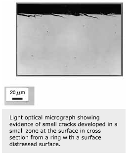
Surface distress indicates surface changes that develop from the accommodation of inhomogeneous, micro-plastic deformation. It develops from the occurrence of many contact events between ring and rolling element when particles are entrained in the Hertzian contact. The main source of this is the presence of small, solid particles in contaminated lubrication. Particle entrapment induces a stress concentration in the surface that yields a local state of stress far above the shakedown limit. The hard steel of the bearing immediately undergoes small amounts of local plastic deformation. This occurs at many locations randomly distributed over the contact surfaces and leads to a very inhomogeneous state of deformation over a thin surface layer. Continuing exposure of the bearing surfaces to these conditions leads to the formation of surface cracks that propagate in the regions adjacent to the deformed surface (typical thickness of about 5-10 mm). Eventually chips of surface material will flake off. The advanced state of surface distress shown in figure 1 is accompanied by an increase in noise produced by the bearing.
Soon after, “wear” may develop and more small metal chips will escape from the surface. This, in turn, contributes to a further increase of noise and to a change in internal clearance of the bearing. Surface distress is a serious failure mode although the damage is concentrated in a small region directly adjacent to the surface. Since crack propagation does not necessarily occur at larger depths, the bearing can still perform its intended function. The surface flakes removed are smaller and thinner by orders of magnitudes when compared with the flakes removed from the surface when spalling takes place.
Spalling
A characteristic appearance of rolling contact fatigue damage is shown in figure 2. The scanning electron microscope (SEM) image shows “spalling damage” in the raceway of a 6309 deep groove ball bearing inner ring. A lump of adjacent surface material has been lost from the inner ring raceway. The width and length of the damaged region varies. In the example shown, the width is about 6 mm (axial direction), and the length is about 15 mm (circumferential direction). The associated depth of spalling is typically in the order of 0.1 to 0.2 mm. Spalling fatigue is typified by major cracks formed below the rolling contact surface which, prior to spalling, might have propagated parallel to the surface where the loading stresses are at a maximum.
Spalling is due to subsurface cracks branching off towards the surface. Alternatively, it is triggered from a surface initiated crack of significant size to bridge the small distance (typically 0.05 to 0.1 mm) from the surface to the altered subsurface zone. Surface damage induced cracks develop from a relatively large dented region in the surface. These dents are created during the crushing of a relatively large-size particle, present in the lubricant, when it is entrained in the contact. The crushing of the particle causes the damaged area around the indented region to be elevated as a consequence of accommodation of the local plastic deformation and residual stress concentrations in the surroundings. Successive rolling contacts can then create a surface crack usually at a spot behind the indented area (with respect to the direction of over-rolling) as shown in figure 3. The surface crack developed from this region is clearly visible. The surface is over-rolled in the direction from bottom to top. Surface cracks of this size range, once formed, might propagate by action of the lubricant penetrating the surface of the crack. The contact load as transmitted by the lubricant can then provide a tensile crack-opening force at the tip of the crack, thereby propagating the crack to a greater depth.
Subsurface induced spalling develops from cracks growing below the surface. These are initiated at the interface between non-metallic inclusions and the steel matrix. The initiation of such cracks is determined by the stress intensity, the coherency of the inclusion with the steel matrix and the capacity of the materials involved for plastic deformation. Before such a micro-crack is formed, micro-yield usually takes place first while maintaining coherency of matrix and inclusion. When the local plastic straining is too severe, however, (such as around a large non-deformable inclusion) it is possible that micro-cracks are initiated. This can happen after the bearing is exposed to initial loading or at a later stage in the fatigue process. In the first case, these cracks usually have only small dimensions and are embedded in a work-hardened surrounding, which can lead to crack arrest. This means crack growth is obstructed. Further propagation follows only then when (cyclic rolling contact loading induced) metal softening occurs. Once spalling occurs the bearing will quickly lose its function.
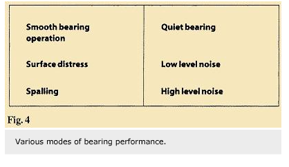
Figure 4 highlights the three regimes determined by noise and vibration analysis. Two bearing fatigue failure modes produce different levels of noise. The condition of bearings can be monitored in service by measuring the noise level. Any increase is then indicative of a change. As such, it can be applied as an early warning diagnostic tool. However, recording the trend in noise development provides no insight into the mechanisms leading to one of the failure modes.
Subsurface microstructural changes
Un-failed bearings run under the same rolling contact loading conditions as in the above example of spalling fatigue failure (fig. 2) showed evidence of local micro-plastic deformation upon analysis of the microstructure. The occurrence of micro-plastic deformation follows from cyclic-stressing induced metal softening known to develop in response to rolling contact loading. It occurs initially in the highest loaded region at a small distance below the rolling track, where the “equivalent von Mises” stress is at a maximum and thereafter in a gradually increasing subsurface volume around that depth. Subsurface cracks appear to be preferentially initiated on the non-metallic inclusions present in this region. The sudden appearance of spalling is then triggered by a crack appearing at the surface either guided by one of these inclusions near to, or intercepting, the surface, or from an indenting event, as shown in figure 3.
With modern clean steel, the greatly improved endurance can be explained by the presence in the highest stressed subsurface volume of significantly fewer non-metallic inclusions of the critical size to cause crack initiation at the levels of stress intensity imposed. Design and life performance models have been adjusted accordingly so allowing higher contact stresses in service. Ultimately, however, spalling fatigue failure still terminates the life of the bearing. Initiation of the associated cracks then occurs on smaller fractions of previously uncritical size non-metallic inclusions inherently present in the steel. The probability of these becoming triggering sites is now increased by two effects: higher contact stress provides higher stress intensities around the sites and the reduction in local yield-limit (metal softening) causes the involvement of more sites of smaller size.
Bearings endurance can therefore only be guaranteed by:
- using clean steel in the manufacturing of bearings;
- ideal bearing running conditions including the provision of clean and adequate lubrication; and
- using steel with a microstructure having sufficient fatigue resistance.
Predicting bearing life
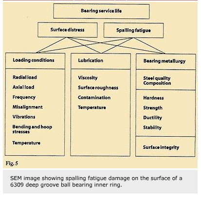
Predicting the life of bearings under service conditions or guaranteeing bearing performance under all kinds of operational conditions is a very difficult task. Striving for smooth and quiet bearing performance over the entire life span of a gearbox, for example, requires control of all the relevant parameters. Even so, it is difficult to calculate the allowable load for a required “service life” with existing life prediction models. For a gearbox design, for example, complexity is introduced by fluctuating dynamic load, misalignment as a result of a less rigid design of the gearbox casing, temperature gradients in the gearbox, different contamination levels in the lubricant at various bearing positions in the gearbox and the susceptibility of the hardened steel to “dent-induced” plastic deformation. Figure 5 highlights a number of factors influencing bearing performance grouped into three categories: loading conditions, lubrication and steel properties.
Only testing the complete gearbox under all possible combinations of torque, temperature and lubrication conditions will provide sufficient information of the bearing performance in service. Occurrence of bearing failure in tests is then corrected by changes in design following a trial-and-error approach.
Alternative approach
An alternative and more efficient approach is to combine testing with performance analysis of bearing components from tests stopped prior to “failure”. This is based on describing changes that might occur in the microstructure, at and below the rolling contact surfaces. Quantitative X-ray diffraction (XRD) methods are highly suitable for this type of analysis. Methods include analysis of the complicated state of residual stress changes occurring in the volume fraction of retained austenite present, changes in the width of the aFe {211} diffraction-line and the analysis of preferred orientation. The analysis provides a measure of the “microstructural response” to bearing service conditions.
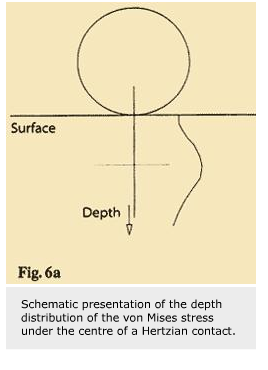
Bearing components subjected to high load and/or temperature will show a subsurface response. The loading sequence evolved in each over-rolling event causes a complex stress situation in the subsurface with the maximum “equivalent von Mises” stress occurring not at the surface but at a predictable depth as illustrated schematically in figure 6a. When the loading stresses are above the micro-yield limit of the steel, micro-plastic deformation will occur altering the microstructure. This happens first at the depth at which the maximum stress occurs, and subsequently in an increasing subsurface volume centred around that depth. Figure 6b shows evidence for microstructural change by the difference in etching response.
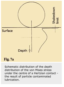
For particle contaminated lubrication conditions, the stresses induced in the near surface region are far above the shakedown limit of the material. Figure 7a shows how the “equivalent von Mises” stress is assumed to develop in this case while figure 7b provides evidence for the existence of small short cracks (not propagating further in the subsurface region to larger depths). These cracks eventually lead to exfoliation from the surface, which is the advanced state of surface distress.
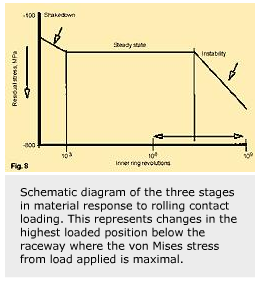
The changes in the steel in response to cyclic stressing develop in three stages; shakedown, steady-state stage and microstructural instability. Figure 8 illustrates schematically the three stages of observable alterations taking place at a depth below the contacting surface where the maximum von Mises stress occurs. The shakedown stage is very short, while the length of the second stage depends strongly on the bearing operating conditions applied (load and temperature) and the steel (alloy and heat treatment).
The most significant of all the changes is the development of residual stress and preferred orientation. Both these changes enhance the probability of crack propagation parallel to the surface. Further, the increase of weakened subsurface volume potentially increases the probability for crack initiation to occur, thereby increasing the probability of spalling fatigue failure developing.
The key issue is the prevention of metal softening in response to cyclic rolling contact loading during service.
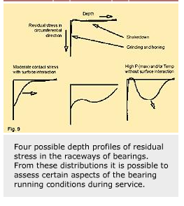
The “X-ray” parameters, already mentioned, are sensitive indicators of loading conditions in the rolling tracks. This method can be used to characterise the severity of operating conditions in the particular application. In the following examples, only the alterations observed in residual stress (one component only) as measured with the sin2 Y method, will be highlighted. Figure 9 shows four possible patterns of a residual stress depth profile as measured below the centre of the rolling tracks in bearing components returned form service. Bearings suffering from surface distress will show alterations in the near surface region. Bearings that have been highly loaded will exhibit a subsurface response. Discrimination is possible between conditions that lead to:
- Surface distress; as developed from particle contamination and micro-slip between the contacting surfaces. Accumulation of only a limited amount of plastic deformation in the surface is possible. Thereafter material will flake away from a thin surface layer (thickness 5-10 mµm) causing the state of surface distress.
- Spalling fatigue;increasing probability of spalling fatigue due to subsurface micro-plastic deformation. The increasing amplitude of residual stress in the normal direction (of tensile nature) and the increase in risk volume, determine the increasing probability for subsurface crack growth consequently leading to spalling failure.
- Endurable running conditions; smooth bearing operation without any change in the microstructure, indicative of well selected bearings for the particular running conditions.
Gearbox bearings analysis
This method of bearing performance analysis is demonstrated in the following examples to optimise bearing applications in an automotive gearbox. Here, the main issue was the higher torque requirements as compared to the original gearbox design, basically an approach of “downsizing”. Figure 10 provides a schematic drawing of the two main shafts in the gearbox. The input shaft is supported by two deep groove ball bearings while the main shaft is supported by one deep groove ball bearing and one cylindrical roller bearing. In this compact gearbox design, one of the deep groove ball bearings on the input shaft and the cylindrical roller bearing on the main shaft are positioned in one bearing support plate, an integral part of the gearbox. All the gearbox bearings are non-sealed. Rings and rolling elements are made of SAE 52100 steel, martensitically hardened and tempered at 170 °C.
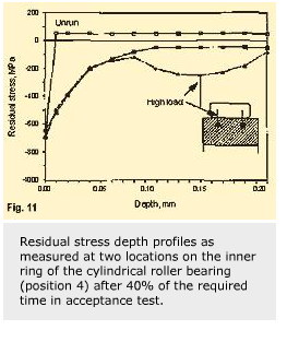
During the acceptance test under increased torque and a complex pattern of variable loads that simulated “worst case” conditions for the application, spalling failure occurred on the raceway of the cylindrical bearing inner ring. Upon examination, a clearly visible band on the cylindrical rolling bearing inner ring was evident and spalling had occurred at several locations in this band all around the ring circumference. The design load for the bearing was found to be very moderate with no failure by spalling fatigue to be expected. This type of failure occurred again when the tests were repeated. Applying the alternative method of material response analysis, a third test was scheduled with the same gearbox. In this case, the loading program was advanced to only about 40% of the required total test duration. In this case, no bearing failure occurred. Upon surface inspection, many indents in the rolling track were found again, indicative of contaminated rolling contact loading conditions. The XRD method for the depth profile measurement of residual stress is shown in figure 11.
This demonstrates how the cylindrical roller bearing suffers from misalignment considering the differences in subsurface residual stress development at the two locations as indicated. Apparently, more micro-plastic deformation was absorbed at one side of the cylindrical inner ring.
This was not expected considering the rigid shafts and stiff bearings applied in this design. Examination of the light alloy support plate disclosed the presence of a slight distortion of the bearing seating. Apparently, during part of the loading cycle, too high a stress occurred in the support plate leading unavoidably to permanent set in the plate. Misalignment of the cylindrical bearing is then inevitable.
A three-fold improvement strategy was devised in this case to solve the problem in one step.
- Increase the support plate thickness with the net effect of reducing the stresses in the plate.
- Adjust the roller geometry by a slight change in the roller profile reducing the probability for edge loading.
- Increase the hardness of the inner ring raceway by a slight change in the heat treatment of the inner rings.
The first two steps should reduce stresses in both the support plate and in the bearing inner ring. The third step is intended to reduce the probability of yield occurring. This is time dependent and does not necessarily increase with increased hardness.
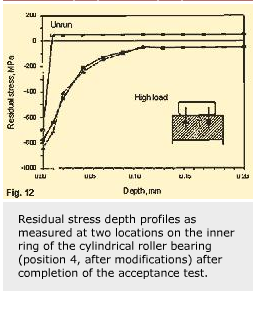
In a fourth test, it could be concluded from the residual stress depth profile (fig. 12) that a solution to the misalignment problem had been found. Bearing failure by spalling did not occur.
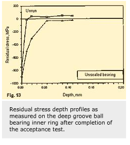
Both figures 11 and 12 show evidence of plastic deformation in the near surface zone (0 to 50 µm). This indicates a significant build-up of residual stress due to the accumulation of micro-plastic deformation in the surface. This phenomenon, as mentioned earlier, is indicative of contaminated lubrication conditions. In this application, the possibility still exists for the development of surface distress and an associated increase in noise level. Continuous use of such distressed surfaces will exacerbate exfoliation, so leading to wear and spalling fatigue.
The deep groove ball bearings at positions 2 and 3 were also analysed for surface appearance and material response. Neither bearing inner ring showed subsurface plastic deformation, but there were indications of an accumulation of micro-plastic deformation in the surface. This trend is less severe compared to that observed in the cylindrical roller bearing. This is attributed to the differences in flow of contaminated lubricant reaching the various bearing locations. One example of XRD clearly indicates the near surface accumulation of plastic deformation (fig. 13). In this case (bearing position 3), a sealed bearing was mounted instead of the open design version. This was possible from the point of view of temperature development within the gearbox, as well as lubricant compatibility. Figure 14 shows how bearing performance can be improved without any noticeable difference in the depth profile compared to that of new bearing inner rings.
In this example, only the changes in the residual stress of one component are used as an indicator of microstructural alterations taking place in the steel response to rolling contact loading. More information can be obtained by following the changes in volume fraction of the various constituents present in the steel matrix, such as austenite and cementite. Also changes in hardness, diffraction-line broadening and possible development of preferred orientation, contribute to further insight into how the bearing behaves during “service” operating conditions. The trends observed are of great value in the development of more advanced bearing life prediction models.
Aat Voskamp,
SKF Engineering & Research Center (ERC),
Nieuwegein, the Netherlands
and Wolfgang Nierlich and Frank Hengerer,
SKF GmbH, Schweinfurt, Germany


