Golden opportunities
Avoiding bearing failure or avoiding reoccurrence may well be worth more than the weight of the bearing in gold.
Every year more than ten billion rolling bearings are produced in the world. Most of them outlive the equipment they are fitted to (approximately 90 %). Some bearings are replaced before they fail (9.5 %). But those bearings that do fail (0.5 %) may have disastrous consequences. When a bearing fails in a main production line of a large factory or in a critical application, (production) losses can amount to millions of euros. Sometimes the underlying cause can be simple.
Take, for example, a goods train derailment that happened several years ago. A bearing in an axlebox overheated (fig. 1), the axle collapsed and eight wagons went up in the air, destroying tracks and catenaries. Traffic was disrupted for hours. Total cost of the damage ran to a few million euros. Luckily, nobody was hurt. The root cause of the problem? It was difficult to determine as almost everything was destroyed, but eventually it was found that during a mainten-ance overhaul a very simple distance ring was fitted that had too small a width. The bearings could shift on the axle and thus developed heat; finally, the shaft (and bearings) collapsed.
Root cause analysis
Rolling bearings are at the heart of most machines and vehicles. But when the bearing goes, the machine or vehicle stops. The reason for this is often that something has happened to the equipment that results in improper functioning of the bearing. The bearing is mostly the “victim”. It is therefore important to find the root cause to prevent it from happening again. The replacement of the bearing alone would not solve the problem.
In service, over a period of time, changes in appearance occur to most bearings. These changes, called patterns, can provide considerable information about the operating conditions and what happened during the bearing life.
To be able to carry out a proper inspection of a damaged bearing, the equipment must be stopped in time. Indeed, once a bearing is damaged, it will gradually deteriorate further until it becomes unserviceable and all evidence of failure mechanisms may well be destroyed. Fig. 2 shows an example.
Foreign particles (contaminants) got into the bearing and were overrolled. This resulted in an indentation (contaminant pressed into the raceway), as well as in a raised rim around the dent that looked somewhat like a crater. The geometry of the raceway was locally changed and as a result that area no longer had a good oil film to separate the contact surfaces. The result was material fatigue, initiated at the surface, with crack formation and eventually spalling behind the damaged area (fig. 2a). With continued running the spalling progressed (figs. 2b and 2c). At a later stage the damaged area became so large that the initiation point, the dent, disappeared (fig. 2d) and inspection of the damaged bearing would no longer reveal the root cause, i.e., contaminants that came into the bearing due to possible sealing problems.
Today, there is a common understanding that:
-
A cause for failure results in certain characteristics.
-
A certain failure mechanism results in a certain failure mode (pattern).
-
From the damage observed, one can possibly determine the root cause of failure.
Much work has been done by ISO to define the different failure modes and to classify them (fig. 3). This has resulted in ISO 15243, published in 2004. When looking at bearing failures, in total six main failure modes can be observed, which can be further classified into a number of sub modes.
The classification is based on three major factors:
-
damage and changes that happened during service (as soon as a bearing has left the factory)
-
characteristic forms of change in appearance that can be attributed to particular causes
-
classified by visible features (including enlargement tools, such as microscopes).
Let’s have a look at the different modes:
Material fatigue
Subsurface initiated fatigue is deterioration of the material. It is caused by cyclic stresses just underneath the raceway surface and ultimately results in decay of the material. Cracks are initiated and propagate underneath the surface, and when they come to the surface, spalling occurs (fig. 4).
Surface initiated fatigue results from inadequate lubrication conditions. The role of the lubricant is to build up an oil film that separates the moving parts. Under poor lubrication conditions, for example due to contamination or wrong viscosity, metal-to-metal contact occurs. The surface asperities (peaks) shear over each other and result in shear stresses at the surface. Due to material fatigue, small cracks and subsequently micro-spalling will occur. Initially, there might be a shiny surface, because the surface roughness is reduced, but the process continues and the surface becomes dull and breaks up more and more (fig. 5).
Wear is a typical aspect that happens in the contact zones of moving bodies. Wear most often is un-avoidable. However, circumstances may cause wear to occur at an early stage of bearing operation. Two variants of wear can occur. These are “abrasive” and “adhesive” wear. They occur due to differences in speed of the working contact surfaces. The cause of the speed differences can be kinematic slip, acceleration and/or deceleration.
Abrasive wear is due to abrasive particles in the lubricant. These can be contaminant particles coming from the outside or inside – for example, wear particles from gears. The abrasive particles wear out the surfaces of the raceways (fig. 6) and rolling elements. This normally results in dull surfaces. However, if the abrasive particles are very fine and hard, such as cement dust, a polishing effect might occur and mirror-like surfaces appear. Often, inadequate (or absence of) sealing arrangements result in
contaminants entering the bearing cavity. A lubricant analysis might reveal the origin of the contamination, which can help in finding the solution for the problem.
Adhesive wearoccurs mainly in contact surfaces subjected to light loads, poor lubrication conditions and with important speed differences, resulting in sliding of the rolling elements. One example is the passage from a rolling element from the unloaded zone into the loaded zone (fig. 7). The rolling element can lose speed in the unloaded zone and accelerate when returning into the loaded zone. This can result in breakthrough of the lubrication film, sliding, heat development and possibly material transfer from the rolling element to the raceway or vice versa. In an early stage the appearance is shiny surfaces, but quickly it turns into a dull surface with (more or less) smeared material.
Corrosion
Moisture corrosion can cause serious bearing damage. In contrast to other damage processes, corrosion can happen fast and penetrate deep into the material. Corrosion occurs in the presence of water, corrosive liquids or moisture. Also high humidity in the air and touching raceways with fingers can lead to this type of corrosion. It’s therefore important to have good protection. Corrosion often happens during standstills and is then visible by corrosion marks at rolling element distance (fig. 8). Deep-seated rust leads to early bearing damage.
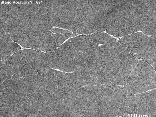
Fretting corrosion can be very harmful. The root cause for its occurrence is micro-movements between two loaded surfaces. Mostly, this frictional corrosion occurs between the bearing outside diameter and housing and/or between the bearing bore and shaft. The micro-movements are mainly caused by the cyclic loads when rolling elements are passing by. Inadequate fits, shaft bending and/or imperfections in the contact surfaces can be the cause and/or accelerate the occurrence. Air can come into the unprotected surfaces, and accelerate the progression of corrosion. The formed iron oxide has a larger volume than pure steel. This can develop material growth and high stresses, even to the bearing raceway and can lead to premature subsurface fatigue. Fretting corrosion can easily lead to ring cracking (fig. 9).
False brinelling, also a frictional corrosion, occurs in rolling elem-ent/raceway contact areas due to micro movements and resilience of the elastic contact under cyclic vibrations. Since it occurs when the bearing is stationary and loaded, the damage appears at rolling element pitch. Depending on the intensity of the vibrations, the lubrication condition and load, a combination of corrosion and wear occurs, forming shallow depressions in the raceways. Normally, the vibration results in local removal of the (protective) lubricant, metal-to-metal contact and abrasive wear. The appearance is therefore usually dull, often discoloured and sometimes reddish due to occurrence of moisture corrosion as well. Occasionally the depressions can be shiny, most likely due to lubricant still present and consequently no abrasive wear occurred. False brinelling damage results in spherical cavities for ball bearings (fig. 10), lines for roller bearings.
Electrical erosion
Any current that goes through a bearing can be harmful.
Damage from excessive voltage can happen when an electric current passes through a bearing, i.e., proceeds from one ring to the other via the rolling elements. At the contact surfaces the process is similar to electric arc welding (high current density over a small contact surface). The material is heated to temperatures ranging from tempering to melting levels. This leads to the appearance of discoloured areas, varying in size, where the material has been tempered, re-hardened or melted. Craters (varying approximately from 0.1 mm to 0.5 mm) are formed where the material has melted (fig. 11).
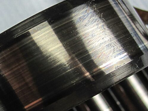
Damage from current leakage results from stray electric currents that pass through a bearing, often caused by frequency variations. The main visual damage is flutes, also called washboard pattern (fig. 12). These flutes have the shape of the contact ellipse in ball bearings and contact lines in roller bearings. The rolling elements are mostly evenly discoloured. Compared to the excessive voltage damage, here the current passes via a larger area and resultantly the current intensity is smaller and the damaging temperature is lower. Therefore the main visual damage is a tempering effect, i.e., a softening of the steel. However, looking at the damage with high magnification shows that mostly there are craters present, as well, on micro scale.
Plastic deformation
Permanent deformation occurs whenever the yield strength of the material is exceeded.
Overload results from static or shock loads and leads to plastic deformation. This can be recognized by depressions at rolling element distance. Often, wrong mounting procedures are at the base of the problem, i.e., applying the mounting force to the wrong ring and thereby producing a shock load over the rolling elements (fig. 13).
Indentation from debris results from foreign particles (contam-inants) that have gained entry into the bearing and are rolled into the raceways by the rolling element. The size and shape of the dents depend on the nature of the particles. The raceway geometry at the dent is destroyed and lubrication is impaired. Stresses arise at the surface and fatigue leads to premature spalling of the surface (fig. 14).
Indentation from handling can occur when bearing surfaces are gouged by hard, sharp objects. Also, bearings must always be handled with care. Although made of highest-quality steel, localized overloads, e.g., from dropping a bearing, might dent the surfaces and make the bearing unserviceable.
Fracture and cracking
Fracture (or cracking) occurs when the ultimate tensile strength of the material is exceeded.
Forced fracture is caused by stress concentration in excess of the mat-erial tensile strength by local overloading or by over-stressing. Two common causes are:
-
rough treatment (impact) when a bearing is being mounted or dismounted. Hammer blows applied to a hardened chisel directly against the ring may cause the formation of fine cracks with the result that pieces of the ring break off when the bearing is put into service.
-
excessive drive-up on a tapered seat or sleeve. As a result of this, the tensile stresses (hoop stresses) arising in the rings produce cracks when the bearing is put into operation (fig. 15).
Fatigue fracture starts when the fatigue strength is exceeded under bending. A crack is initiated that will then propagate. Finally, the whole ring or cage cracks. Fatigue fracture can occur when a tight fit has been used, leading to high hoop stresses. Then, the combined Hertzian and hoop stresses can lead to premature fatigue and through cracking of the ring.
Thermal cracking can occur when two surfaces slide heavily against each other. The frictional heat that is developed causes cracks, generally at right angles to the sliding direction (fig. 16).
Conclusion
A large percentage of bearing failures can be avoided. In-depth root cause bearing damage analysis might reveal the root cause, and by taking the proper action reoccurrence of bearing failure can be avoided.
Maintenance tips
By applying some basic maintenance rules, bearing service life can often be extended.
-
Respect the specifications: A bearing is made to take a certain load, rotate at a certain speed, etc.
-
Do not put too heavy (or too low) a load on a bearing or rotate it too quickly. There is a large choice of bearings. It is important to select the one that fits the application. Make sure the right toleran-ces and fits are applied.
-
Where applicable, make sure alignment is within appropriate limits.
-
Cleanliness: A clean environment during the mounting process provides a good start for long bearing service life.
-
Tools: Always use the appropriate tools during mounting or dismounting. Inappropriate tools might lead to early bearing damage.
-
Sealing: Make sure that the right sealing solution has been chosen and that it works effectively.
-
Lubrication: Efficient lubrication is of utmost importance. Too little, too much or inadequate lubrication can result in early bearing damage. Make sure the right lubricant is applied, at the right time and in the right quantity