Bearing damage analysis: ISO 15243 is here to help you
Being able to identify failure modes and causes of rolling bearing damage is the first step towards avoiding repeat failures and improving machinery reliability.
Bearings are one of the most common elements in modern industrial machinery. They connect the rotating part (shaft) to the stationary part (housing) with minimal friction. They allow for the smooth running of machinery ranging from cars and aircraft to generators, conveyors, printing presses and any kind of machinery or equipment that rotates.
People working with industrial machinery would do well to gain a better understanding both of how they work and how they sometimes fail prematurely in operation.
With this in mind, the International Organization for Standardization (ISO) has published ISO 15243, a standard that provides a classification of the different failure modes that occur in rolling element bearings. For each failure mode, the standard describes the characteristics, appearance and possible causes of the failure. The most recent version of the standard was published in 2017.
As well as understanding the characteristics and appearance of a failure mode, it is important to understand what caused the failure. With this understanding, recommendations for corrective actions to help avoid the failure in the future can be taken. Of course, if the bearing is run to failure and seizure occurs, then it may be impossible to identify the failure mode and causes.
Here we provide a summary of the ISO failure modes for rolling bearings as well as their causes. But first some basic information.
Bearing basics
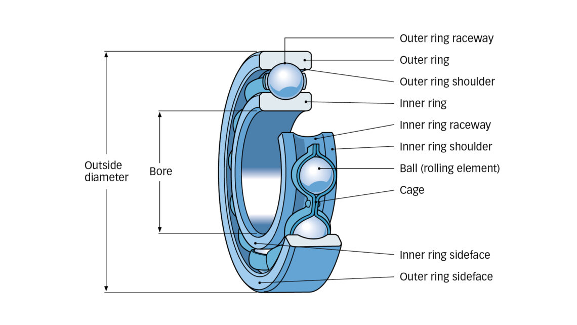
Rolling element bearings are high-precision machine elements made of high-hardness bearing steel and, in more cases now, with ceramic rolling elements. A bearing comprises inner and outer rings, balls or rollers and a cage and, optionally, is capped with seals or a shield. Figure 1 shows the common parts of a rolling bearing. Capped bearings are grease-filled by the manufacturer. Lubrication, grease or oil is crucial to the development of the lubricating film thickness needed to separate the rolling elements and raceways. A bearing must be selected specifically for the machine, fitted and installed properly and well lubricated and free of contamination. A proper understanding of bearing internal geometry and how the bearing is meant to operate is important when looking for signs of damage.
Causes for failure
What stops a bearing from operating correctly and subsequently leads to its failure?
It is also important, and perhaps more important, to understand what caused the failure than the failure mode itself.
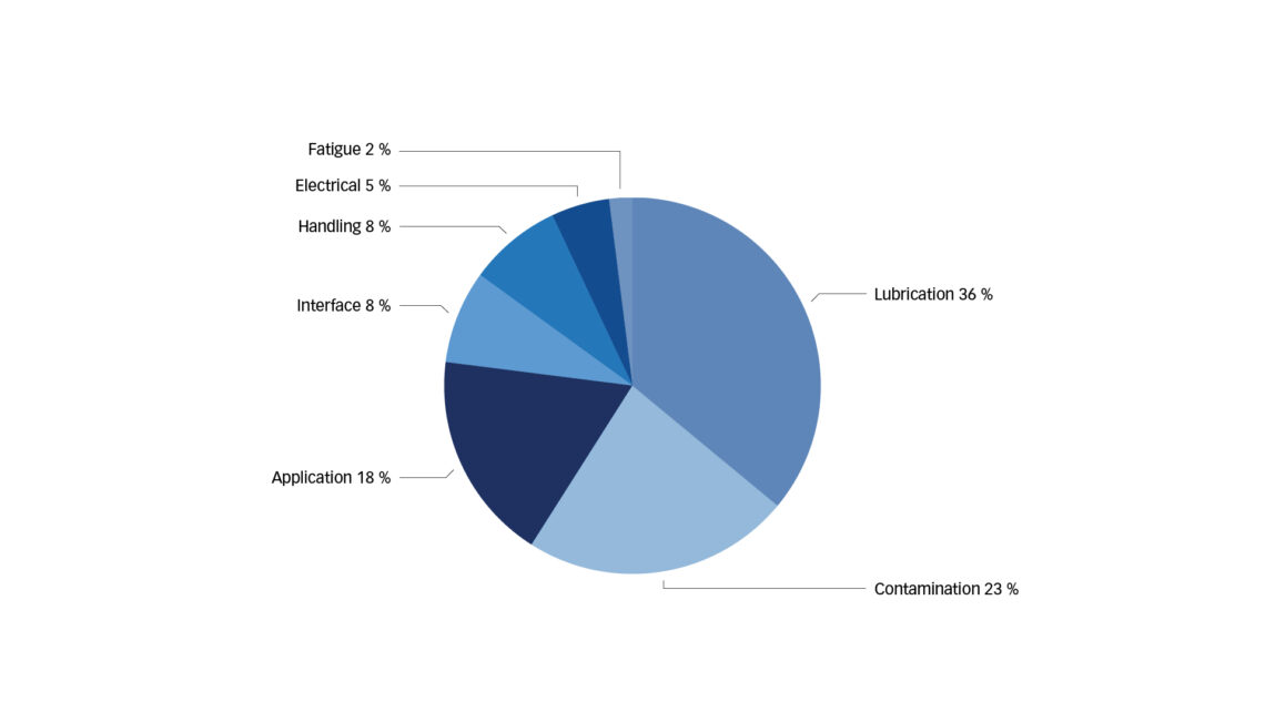
There are different answers to this question, depending on whom you ask. SKF does many bearing inspection and damage analysis investigations for customers and for our own research. SKF documents the investigations in a cloud-based software – Bearing Analysis Reporting Tool (BART). The reasons bearings are removed from operation and the causes for a bearing’s removal are tracked, along with a score of other data. With this data, SKF can give some answers to the question: Why does a bearing stop operating?
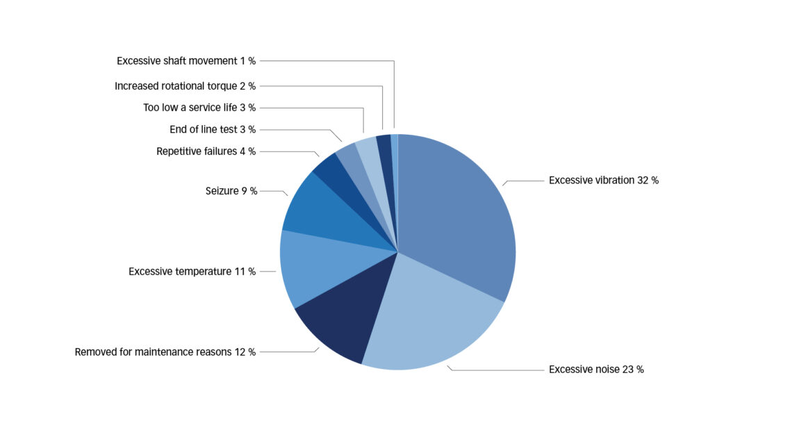
The data shows that most bearings are removed from operation because of excessive vibration and noise. Bearings are also removed from operation when maintenance is done on the machinery or when excessive temperature is experienced (fig. 2).
ISO 15243 failure mode classification during bearing operation
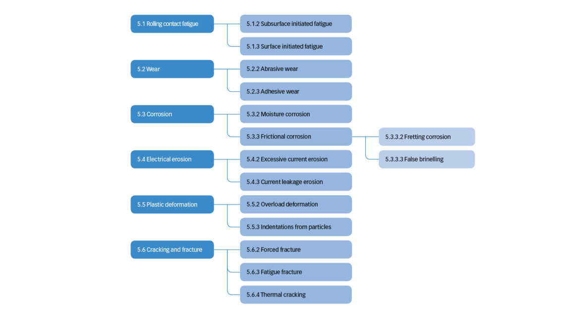
ISO 15243: 2017 [Ref. 1 ] classifies the failure modes that occur while the bearing is installed in the asset/machine and during operation, meaning that it does not include manufacturing-type defects such as missing parts. The ISO failure modes are divided into six categories: rolling contact fatigue, wear, corrosion, electrical erosion, plastic deformation and cracking and fracture (fig. 4). Each of these is divided into subcategories for more specific classification of the failure modes.
The numbering (e.g., 5.1.2) of the classifications is based on the ISO 15243 Chapter 5.
The handbook Bearing damage and failure analysis [Ref. 2] can be useful to identify the bearing failure mode and causes.
The six classifications are described as follows:
Rolling contact fatigue (ISO 5.1)
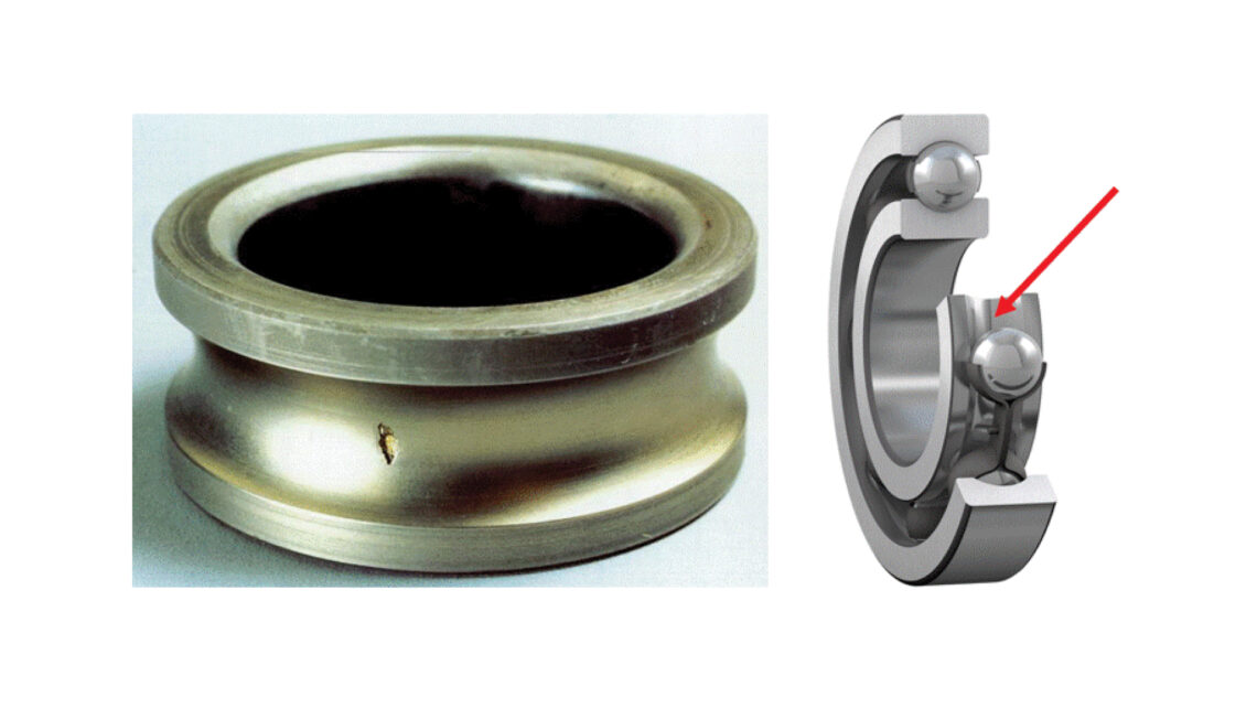
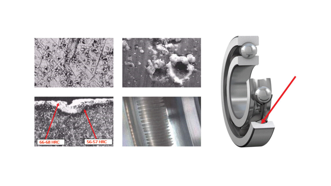
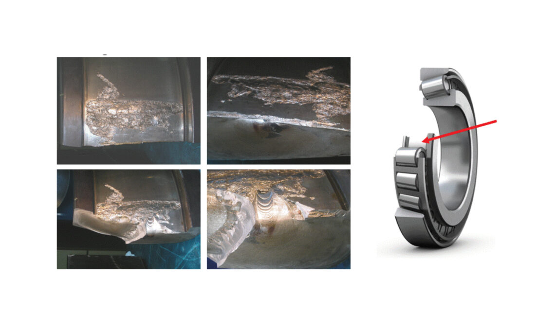
Rolling contact fatigue is classified in two subcategories: subsurface initiated and surface initiated fatigue. Subsurface initiated fatigue (ISO 5.1.2) (fig. 5) is caused by the cyclic loading of the rolling contact surfaces, which over time causes a material structural change where microcracks initiate. The microcracks develop below the surface, often at an inclusion in the material, and propagate to the surface as spalls. The fatigue is influenced by the bearing quality, applied loads, lubrication and cleanliness. This is akin to the bearing rating life, L10mh. The subsurface fatigue can be accelerated if the bearing is subject to high stresses due to, for instance, temporary overload or another event that weakens the material. In these cases, the fatigue life is short (5 % to 10 % of L10mh). Surface initiated fatigue (ISO 5.1.3) (fig. 6) is fatigue initiated on the rolling surface and is typically caused by surface distress due to poor lubrication or poor cleanliness. Inadequate lubricating film and overrolling of solid contamination can result in metal-to-metal contact, causing the surface asperities to shear over each other. Thereafter microcracks can occur, followed by microspalls and finally surface initiated fatigue.
Wear (ISO 5.2)
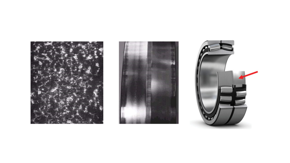
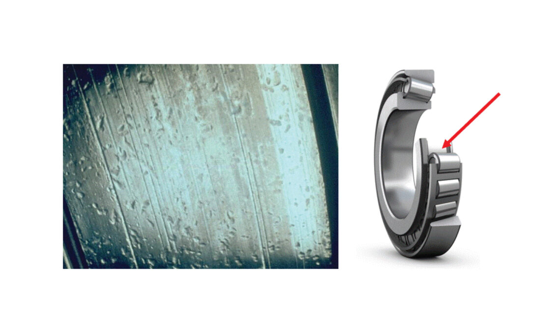
The next category is wear. The ISO classifies wear into two subcategories: abrasive wear and adhesive wear. Abrasive wear (ISO 5.2.2) (fig. 7) is the progressive removal of material, usually in the presence of abrasive material such a particle contaminant. Abrasive wear can also occur because of inadequate lubrication. Abrasive wear is generally characterized by the dull appearance of the surfaces. Abrasive wear is a degenerative process that can eventually destroy the microgeometry of a bearing’s rolling surfaces. Abrasive particles can quickly wear down the raceways of rings and rolling elements as well as cage pockets. Abrasive wear can be caused by the ingress of contaminated material into the lubricant and bearing and a starvation of lubricant in the rolling contact.
Corrosion (ISO 5.3)
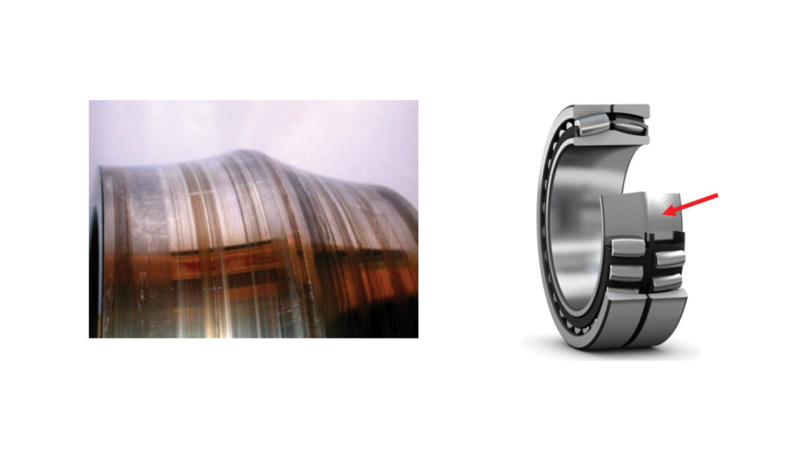
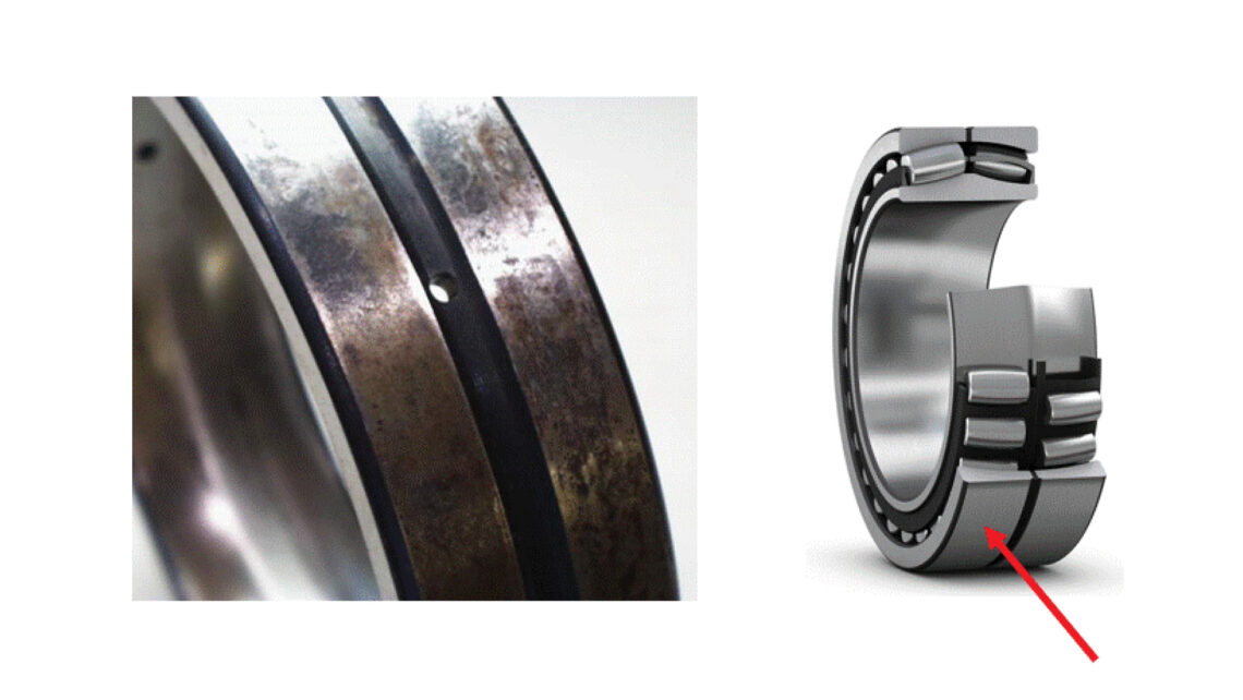
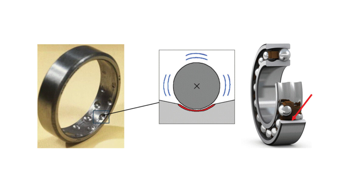
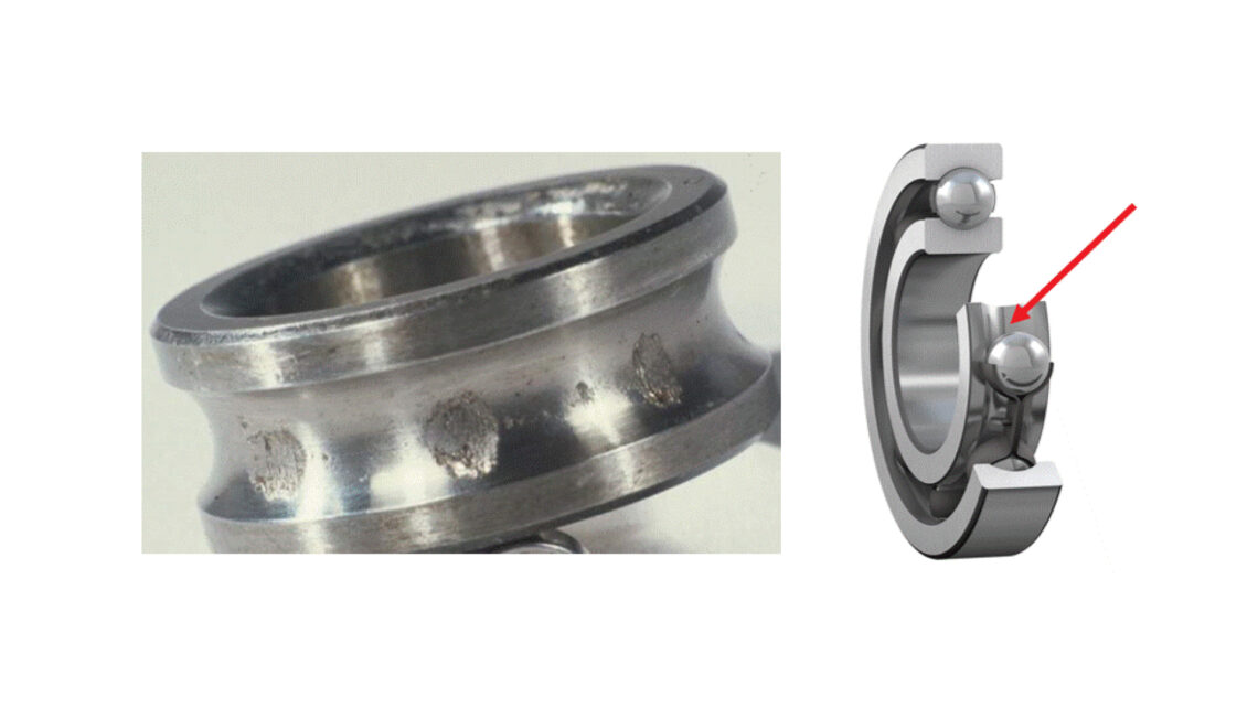
The next category, corrosion, is classified into three categories: moisture corrosion, friction corrosion and false brinelling. Moisture corrosion (5.3.2) (fig. 9) is a classic issue of moisture ingress into the bearing. The high hardness bearing material has low corrosion resistance. The moisture will cause damage on rolling element spacings when the bearing is at a standstill. The surface deterioration can lead to surface initiated fatigue in subsequent operation. Moisture greatly degrades the capability of the lubricant to develop a film thickness in an operating bearing. Fretting corrosion (ISO 5.3.3.2) (fig. 10) occurs when there are micromovements in an interface between mating surfaces, such as between the bearing inner ring and shaft and bearing outer ring and housing. This can be due to incorrect fitting of the bearing on the shaft or in the housing, depending on the applied load. For instance, a bearing with a rotating inner ring and a steady applied load requires a certain minimum interference fit of its inner ring on the shaft to avoid fretting corrosion. Likewise, a bearing with a rotating inner ring and a rotating applied inner ring load requires a certain interference fit of the bearing outer ring in the housing to avoid fretting corrosion. Fretting corrosion appears as a red/blackish oxidization in the interface. False brinelling (ISO 5.3.3.3) (fig. 11) occurs in the contact area between the rolling elements and raceway subject to small oscillatory motion or vibration. The wear occurs on rolling element spacings. The wear removes the original manufacturing finishes of the surfaces and can also have a red/blackish oxidization on the surfaces, similar to fretting corrosion. The amount of wear is dependent on the intensity of the applied load, intensity of the oscillation and vibrations and the lubrication conditions.
Electrical erosion (ISO 5.4)
There are two classifications of electrical erosion: excessive current erosion and current leakage erosion. Excessive current erosion (ISO 5.4.2) (fig. 12) occurs when current passes through one bearing ring, through the rolling elements and through the other bearing ring. At the contact surfaces, the process is similar to electric arc welding (high current density over a small contact surface). The material is heated to temperatures ranging from tempering to melting levels. This leads to the appearance of discoloured areas that vary in size, where the material has been tempered, rehardened or melted. Craters form where the material has melted and consequently broken away due to the rotation bearing. The excess material wears away. Excessive current erosion can be caused by lightning strikes on the machinery, when weld repairs are made on machinery with improper grounding of the welding equipment, etc. Current leakage erosion (ISO 5.4.3) (fig. 13) occurs when somewhat low intensity current passes through the bearing. The damage is typically small craters positioned near one another, and a grey/washboard pattern appears over time. The rolling elements can have a grey, dull appearance and the lubricant can become discoloured. The extent of the damage depends on the current intensity, duration, bearing load, speed and lubricant. Current leakage erosion is common in electric motors having stray currents when the shaft is not properly grounded and the motor is controlled by a variable frequency drive.
Plastic deformation (5.5)
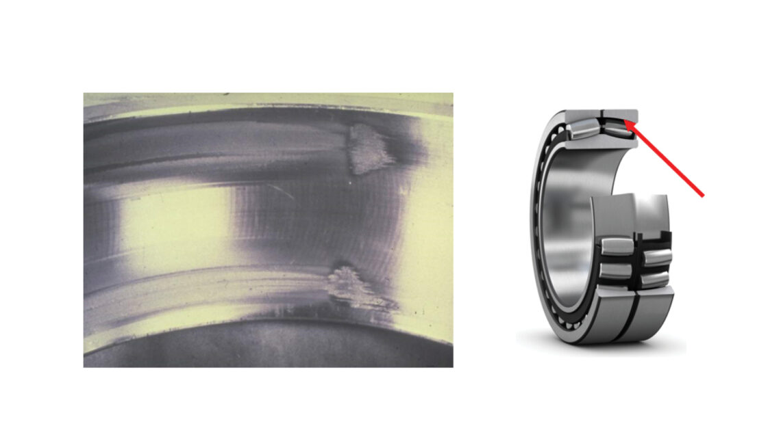
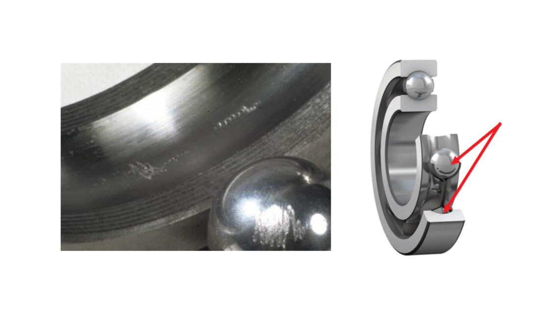
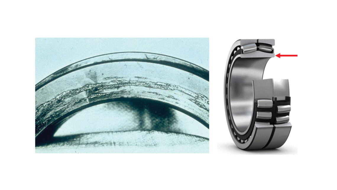
The ISO classifies plastic deformation into two categories: overload deformation and indentation from particles. Overload deformation (ISO 5.5.2) (fig. 14) is mechanical damage caused by static overload such as from improper handling (bearing dropped from height), improper mounting (hammering on bearing), peak loads from the machinery operation, etc. It can manifest itself as raceway indentation or nicks on rolling element spacings, damages to cages, seals and shields, etc. Indentations from particles (ISO 5.5.3) (fig. 15) occurs when solid particle contaminants or debris are overrolled in the bearing’s rolling contact area, thus causing indentations (deformations) in the raceways and rolling elements. The size, type and hardness of the particles influences the scope of the damage. Subsequent overrolling of the indentation can lead to surface initiated fatigue (ISO 5.1.3).
Cracking and fracture (ISO 5.6)
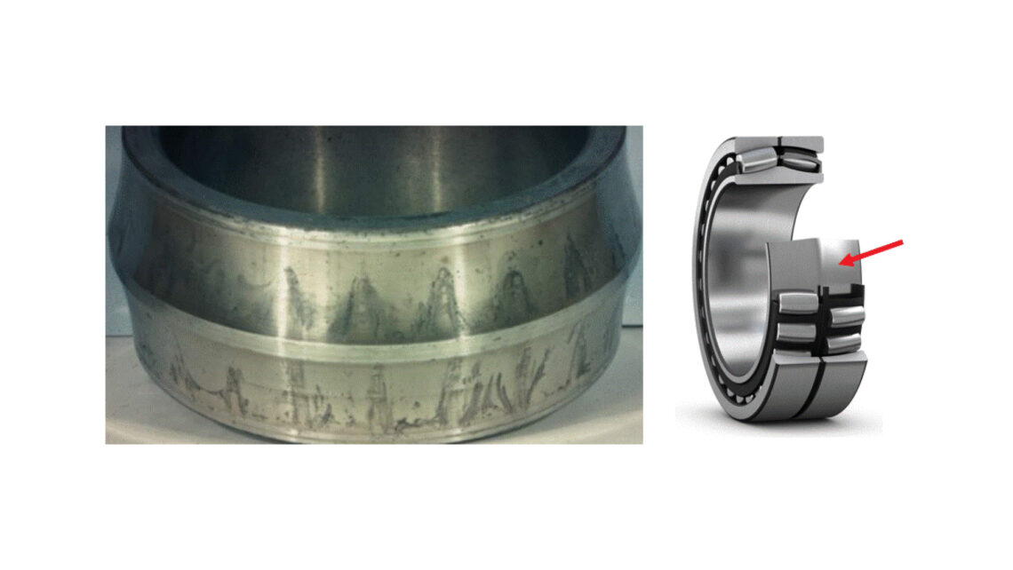
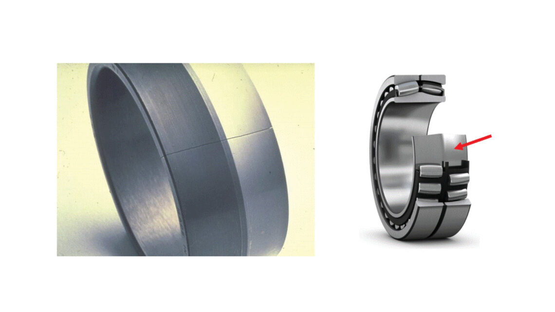
The final ISO category is cracking and fracture. It is classified into three categories: forced fracture, fatigue fracture and thermal cracking. Forced fracture (ISO 5.6.2) (fig. 16) results when stresses exceed the tensile strength of the material. Common causes of a forced fracture are too high a hoop stress from mounting a bearing on a shaft with excessive interference fit or driving a tapered bore bearing too far up its tapered shaft seating or mounting sleeve. Fatigue fracture (ISO 5.6.3) (fig. 17) occurs when the fatigue strength of a material is exceeded under cyclic bending. Repeated bending causes a crack that propagates through the ring or cage. This can occur in a bearing if it is subject to heavy applied loads and the supporting housing does not provide uniform stiffness, subjecting the outer ring to high cyclic stresses. Thermal cracking (ISO 5.6.4) (fig. 18) occurs when two surfaces slide against one another, generating frictional heat. If the sliding is substantial, local rehardening of the surfaces in combination with the development of high residual tensile stress causes cracks, which are generally at right angles to the direction of the sliding. Thermal cracking can occur if a stationary housing, for instance, comes into contact with the rotating bearing ring.
A more thorough description of the bearing failure modes and causes can be found in Reference 2.
Keep in mind that the lubricant (oil or grease) from within the damaged bearing can also provide insight in the bearing investigation. A lubricant sample should be taken for comparison with the fresh sample. A lubricant analysis can be made to consider particle and moisture contamination content, changes in viscosity, change in grease consistency, etc.
Examination of the bearing seals or shield and other components such as the sleeve might also be informative.
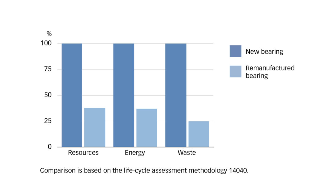
Predictive maintenance or condition-based maintenance techniques such as vibration analysis, thermography, oil analysis, etc., can be used to detect faults before severe bearing damage occurs and possible damage to the asset the bearing was operating in also occurs. This can allow for improved failure mode identification. Removing larger size bearings (bore > 200 mm) from operation before extensive damage occurs might allow them to be remanufactured. This can restore the bearing to a “like new” condition, reducing maintenance costs and environmental impact (fig. 19).
Most common failure modes
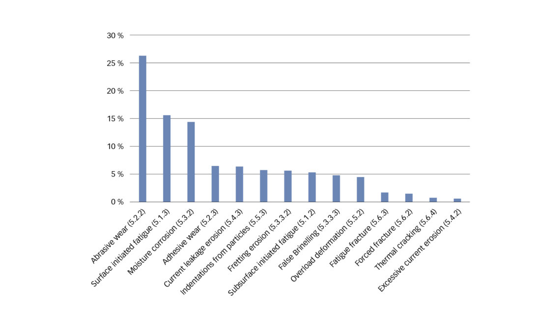
SKF’s data1 identifies the five most common ISO failure modes to be abrasive wear (26 %), surface initiated fatigue (16 %), moisture corrosion (14 %), adhesive wear (7 %) and current leakage erosion (7 %) (fig. 20). These failure modes represent approximately 70 % of all the failure modes identified in the bearing investigations, although fretting corrosion is seen in most bearings, even if minor in nature. The other ISO failure modes are observed but to a lesser extent.
SKF Bearing Analysis Reporting Tool (BART)
The SKF BART software is deployed to SKF engineers and is now available to SKF customers. The customer is provided basic training on bearing knowledge, bearing inspections techniques and the use of the SKF BART software. The customer works closely with an SKF application engineer or specialist to complete the inspection report. The BART Inspection report is approved by the SKF expert. The inspection can reveal whether the bearing should be replaced, can be reused, is a potential for remanufacturing or must be scrapped. It can also be used to document the inspection of a new bearing before it is placed in service. This can be helpful if a bearing has been in storage for a long time.
If needed, a full bearing damage analysis can be made by an SKF application engineer to provide recommendations for reliability improvement. The SKF engineers can use artificial intelligence (AI) [Ref. 3] to augment their bearing damage analysis. The AI uses a computer vision system that can evaluate bearing damage using digital photographs. The system uses artificial intelligence in the form of a neural network image-recognition algorithm that has been trained using thousands of images of damaged bearings from SKF’s archives.
Summary
In summary, the ISO 15243 is useful to classify the failure modes of rolling bearings that have operated in assets and can be helpful to identify the failure causes. By acquainting oneself with the common bearing failure modes and their causes, one can take corrective actions to avoid a repeat of the failures. This can greatly reduce the risk of unplanned and catastrophic failures and potentially improve the reliability and availability of the assets. Bearings that are removed from operation for maintenance reasons can be inspected for reuse or possibly for remanufacturing.
Bearing failure mode and cause data and other related data are being collected to gain better insights on bearing operations. The SKF BART software is used by SKF and is available to customers to make bearing inspection and damage analysis reports.
1 SKF Bearing Analysis Reporting Tool
References
[1.] International Standard ISO 15243:2017, “Rolling bearings damage and failures – terms, characteristics and causes”
[2.] SKF brochure 14219, “Bearing damage and failure analysis”
[3.] SKF Evolution article, “The future of bearing failure analysis is here” (2022)


