Dynamic tests to evaluate hub bearing units
Dynamic testing of automotive hub bearing units contributes to an accurate prediction of the operating characteristics of individual designs.The SKF group has been actively involved in the development of advanced wheel bearing units for many years. The trend has been to create integrated hub bearing units through the addition of structural and torque transmission functions to wheel bearings.
Dynamic testing of automotive hub bearing units contributes to an accurate prediction of the operating characteristics of individual designs.The SKF group has been actively involved in the development of advanced wheel bearing units for many years. The trend has been to create integrated hub bearing units through the addition of structural and torque transmission functions to wheel bearings.
The requirements of such automotive units are an adequate service life and an ability to function under all peak load situations. Hub bearing units must be dimensioned such that a safe failure mode will occur (such as raceway spalling or pitting as a result of rolling contact fatigue) before an unsafe failure mode such as flange fracture.
A balance is required between weight and performance so that hub unit life matches that of the vehicle. This means that dimensioning should not result in an over-designed product that would introduce cost and weight penalties and have a consequent effect on overall vehicle performance.
Performance testing
Along with hub unit development has come a parallel development of suitable test methods and standards to study all aspects of hub bearing unit performance. This encompasses bearing life, flange fatigue, stresses, seal and grease performance.
During the early development phase of hub bearing units, block programs with constant load and speed are used. The loads used for these tests are selected according to the vehicle of interest. Such tests can be performed with relatively low-cost test machines; thus statistical evaluation of a large number of tests can result in an accurate estimation of the L10 life (90% survival) of the units under test.
The dynamic performance is also important. This includes the interaction of bearing and constant velocity (cv) joints which is the performance of the connection between the bearing and the cv joint. Dynamic simulation testing was adopted as the principal method of analysis because less sophisticated methods using simplified load cases did not correlate closely enough to actual service performance.
Dynamic simulation
The main purpose of any dynamic simulation test is to reproduce accurately a service environment that has been recorded using an instrumented vehicle. This can be achieved in two ways. The first is by reproducing the measured frequency spectra – that is, the amplitude-frequency characteristic of a particular parameter, termed frequency domain simulation. The second technique is by reproducing the measured time history called time domain or real time simulation.
For automotive hub units, time domain simulation is the only method considered to guarantee correct reproduction of a multi-parameter response in both amplitude and phase. Consequently, DYANA, a dynamic simulation system, was developed to test wheel bearing and cv joint service conditions. This system is capable of applying the six most important load and attitude parameters acting on the wheel bearing and cv joint assembly to four test specimens that comprise the wheel bearing, hub, cv joint, drive shaft and plunge joint.
System concept
The system concept is based on the “four square” principle, a common technique used in drive line component testing to reduce power consumption. Simultaneous reproduction of the six load and attitude parameters, in terms of amplitude and phase, requires the use of a drive signal control system known as remote parameter control (RPC). RPC is a commonly used technique within the automotive industry for testing vehicles and drive line components.
Mechanical system
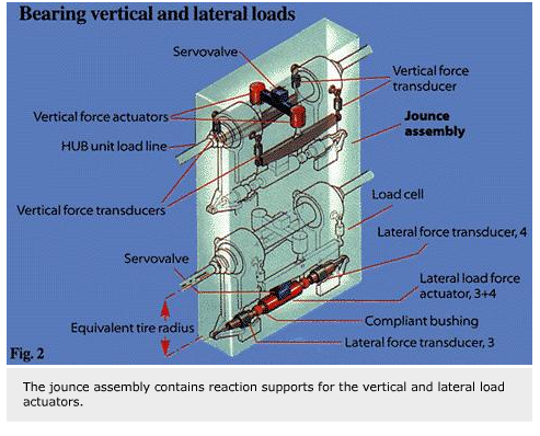
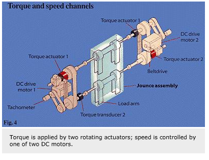
Four test specimens are mounted into the central jounce assembly of the DYANA system. The jounce assembly contains reaction supports for the vertical and lateral load actuators complete with load cells and couplings, and the bearing monitoring transducers. The upper and lower pairs of specimens are connected via two toothed belts to form the four square torque loop.
Mechanical adjustments can be made to accommodate drive shaft length, tyre rolling radius, steering offset, wheel vertical load line position and steer axis. A dedicated hydraulic power supply delivers hydraulic pressure to the actuators. This is of conventional design with two variable displacement pumps.
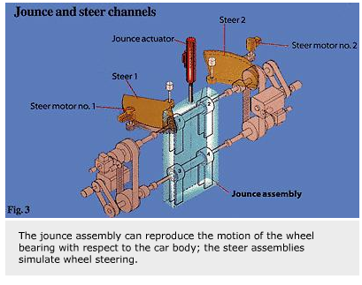
Each torque actuator/DC motor assembly is supported in a “C” frame pivoted to rotate about an adjustable vertical axis to provide the steering motion. In this configuration the “car” is made to move around the fixed bearing. The “C” frames are driven via planetary gears and a chain drive, by a hydraulic motor. Angular displacement transducers on each “C” frame are used to provide feedback for the two independent servo control loops.
The jounce motion of the wheel bearing with respect to the car body is simulated by vertical movement of the whole jounce assembly. Feedback for the jounce controller is provided by a displacement transducer located within the vertical actuator.
Vertical bearing force is applied per pair of hub units by two actuators controlled by a single servo valve. Each actuator acts on a cross beam, parallel to the support shaft so that its shares its load between the two test units. Each hub unit has two load cells in the vertical load transmission from the cross beam. These load cells are wired to form one transducer. Its output is combined with that of the transducer on the second unit to provide the feedback signal for the servo control loop.
Lateral bearing force is applied by a single two-ended actuator per set of two hub units. Each actuator rod is connected at both ends to the “load-arm” via a compliant bushing and an outboard load cell. The two force signals are averaged, after signal conditioning, to provide one feedback signal for the servo control loop.
For the application of torque, two rotating torque actuators are used to eliminate the inertia of the toothed belts and pulleys in the torque chain. This increases the operational frequency of the torque channel. Torque is measured by two transducers at the opposite ends of the driveline from the actuators. In this case, the average of the two measured torques is used as one feedback for the two servo controllers.
Finally the rotational speed of the drive shaft is controlled by one of the two DC drive motors, the feedback signal being given by a tachometer. The second DC motor operates in current control, which means that the current is made equal to that required by the speed control motor so that both motors supply equal torque to the loop. This configuration significantly reduces torque differences around the loop.
Electronic systems
Both analogue and digital electronic systems are used in the test procedure. The analogue system performs four basic functions. It assures correct hydraulic pressure to all rig channels and provides command signals to the channel controller. It monitors the whole system. In the case of specified abnormal conditions, it shuts down the system in a controlled manner. In addition, it displays all analogue command, feedback and monitoring signals.
The digital part of the control system comprises two independent digital computers. The first computer has the job of providing the remote parameter control (RPC) function and data analysis. This includes digitising and analysing data from recording tapes, editing the information to desired response signals and converting data to the six test rig parameters. Finally this computer corrects the data for rig dynamics using the RPC process.
The second computer is used to run endurance tests, monitor specimen and test rig conditions, update the trend monitoring data file and record short-term trends in a “flight recorder” file.
A background program provides the actual test monitoring during the time that a separate foreground program is commanding the test. Two levels of monitoring are provided.
Short-term monitoring results in temporary response data storage of the current drive file to a flight recorder-type file that is constantly over-written. This file can be accessed later to determine the sequence
of recent events.
Long-term monitoring analyses the response data and calculates the statistical information – averages, maximum and minimum values, rms, times above and below set levels – for each channel over a complete drive file to determine the long-term trends and progression to failure. This program also compares these statistics with pre-set limits which, if exceeded, cause the test rig to be stopped.
Durability testing
Durability testing on automotive hub units allows various road surfaces to be simulated by combining different drive files. Typically, a drive sequence would contain a period of town driving followed by a short period of pave driving.
The frequency ranges used for these drive files are dependent on the frequency response of the particular test arrangement. Such factors as torsionally weak drive shafts can enforce restrictions on the maximum frequencies that can be simulated. Typical frequency ranges, however, are as follows – torque, jounce, lateral force and vertical force: 0-20 Hz, speed and steer: 0-5 Hz.
Although it is feasible to reproduce any service environment using this method, the use of standard test files is preferable because this permits cross-correlation of one test with previous ones. Thus, comparisons can be made between different unit designs under repeatable test conditions. This is a considerable advantage when compared to field testing. The ability to run the test on a 24-hour basis means that test results can be obtained in a shorter time than with field testing.
The selection of the particular test conditions to be applied is crucial, however. Conditions are normally chosen to represent typical road surfaces or events. Accurate reproduction of the service loads and speeds is not proof that a simulation test is valid. In all simulation tests some assumptions must be made regarding the non-controlled parameters, such as ambient temperature and the influence of surrounding components that can affect performance. The simulation process is only valid if the test conditions chosen can reproduce the same failure mode as that which would occur during normal service.
End of pass tests
In addition to drive simulations, so-called “end of pass” tests can be performed. These computer files are designed to steer the test machine through a set sequence of loads, speeds and displacements such that the condition of the test units can be evaluated under quasi-static conditions. This greatly simplifies the evaluation of the condition of a bearing unit and the associated cv joint.
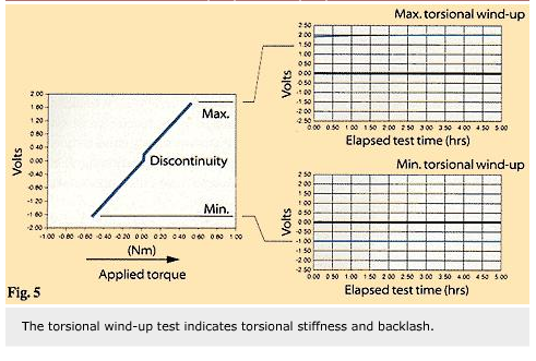
A torsional stiffness test is an example of such a test. This checks for backlash in drive line assemblies. A saw tooth variation in torque is applied to the system to all four test specimens simultaneously. The total torsional wind-up – that is, the angular twist of all four drive lines and the torque actuator system – is measured using a rotary displacement transducer.
A typical plot of torque against torsional wind up would show that both the torsional stiffness of the system and the presence of a discontinuity is the result of clearance or backlash in the system. Monitoring of the minimum and maximum wind up using the trend monitoring system software is used to indicate any increase in system backlash.
A review of the DYANA system was carried out after five years’ of operational experience. When the test system was originally designed, it was decided not to include steering knuckles, as this would over-complicate the test arrangement. However, in various projects the system was modified to include steering knuckles to be mounted at two positions. Overall the rig has proved a valuable tool in assessing the merits of various hub unit designs.
Wilco van Dalen,
SKF Engineering & Research Centre (ERC),
Nieuwegein, The Netherlands


