Increased service life of hydraulic cylinders through friction-optimized buffer seals
In hydraulic systems, fluids are being pressurized to generate, control and convert fluid power into recip-rocating movement. The efficiency is defined by energy output related to energy input. Seals can strongly influence this energy efficiency.
Seals are the barrier between pressurized areas in a hydraulic cylinder and are in direct contact with the movable parts (piston rod and piston). The seals create friction forces that act against the movement and decrease the energy output. But it’s not only the energy output that suffers under increased friction; the operating temperatures are also higher, resulting in the decreased service life of the whole hydraulic sealing system. Furthermore, the increased temperature influences the properties of the lubricant, especially the viscosity of the oil, which results in a decreased lubrication behaviour and less energy output. Apart from this, fluctuations in friction, known as stick-slip, can influence the exact positioning and/or create noise.
Sustainability – a word that is becoming more and more important – has reached nearly every area around the world. A sustainable hydraulic system must be free of leakage, but also the interval between maintenance stops must be extended to the longest possible time period. From the seal point of view this can be reached by selecting the best possible sealing system – consisting of rod and piston seals as well as guide elements and static seals – to reach the greatest efficiency. Therefore, not only must the seal types themselves be understood but also the interactions between those different seal types must be well known to reach the target of a highly efficient sealing system.
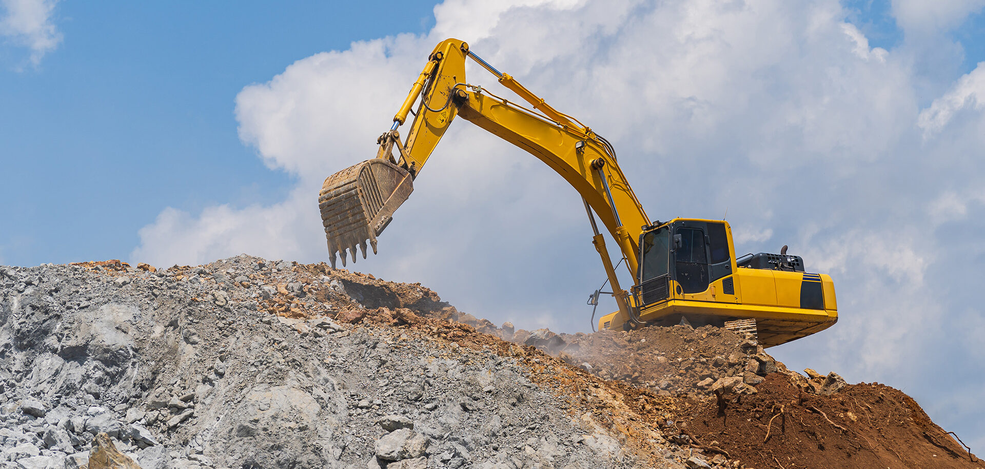
This article focuses on rod sealing systems used in hydraulic applications (e.g., excavators). In particular, the interactions between the buffer and the primary rod seal were thoroughly investigated at in-house test rigs and in FEA studies. The outcome of these investigations resulted in two new friction-optimized buffer seals from SKF.
Hydraulic rod sealing system and main sealing
functions
The rod sealing system in a hydraulic cylinder typically includes a buffer seal, a primary rod seal and a wiper (fig. 1).

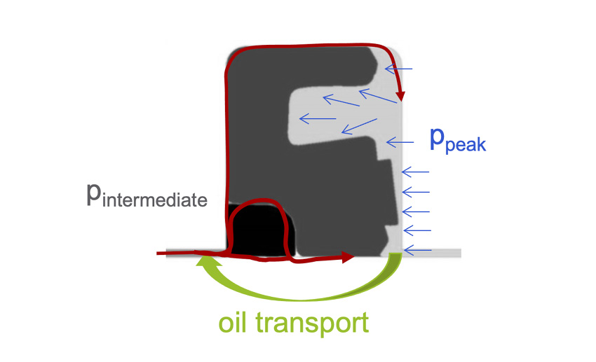
- absorb system pressure spikes (ppeak) that could damage the primary rod seal;
- allow oil transport past the sealing lip to provide lubrication to the primary rod seal and the wiper (fig. 2); and
- vent intermediate pressure (fig. 1) between the buffer seal and the primary rod seal when the system pressure is lower than the intermediate pressure to prevent a pressure trap.
- prevent leakage by reducing lubrication film thickness and allow back-pumping into the system;
- balance lubrication film thickness to have the lowest possible leakage on the one hand and low friction on the other hand; and
- absorb possible occurring intermediate pressure.
The wiper must provide these primary functions:
- exclude all kinds of contamination coming from the environment;
- prevent leakage by having the ability to pump lubricant back into the system; and
- vent possible occurring intermediate pressure between rod seal and wiper.
Buffer seal types
To fulfil the above-mentioned buffer seal functions and the overall target of a highly efficient rod sealing system, the buffer seal needs to be designed in such a way as to ensure a certain lubrication film to the primary rod seal and the wiper.
Generally, there are two different buffer seal types available on the market, which work in different ways based on their special design features. The first type is called a “high-sealability buffer seal”. It focuses on reducing the lubrication film to a minimum and therefore preventing the primary rod seal from being pressurized. This concept prevents extrusion and/or wear of the primary rod seal caused by pressurization, but it also leads to starved lubrication of the rod seal, resulting in increased friction and possibly stick-slip and higher system temperatures.
The second type is called a “friction-optimized buffer seal”. This concept allows a certain lubrication film past the sealing lip and ensures enough lubrication to the primary rod seal. This concept can lead to a possible occurring intermediate pressure behind the buffer seal that must be taken from the primary rod seal, but it ensures a reduced friction of the whole rod sealing package, resulting in increased lifetime and greater energy efficiency.
1.1 Friction-optimized buffer seals from SKF
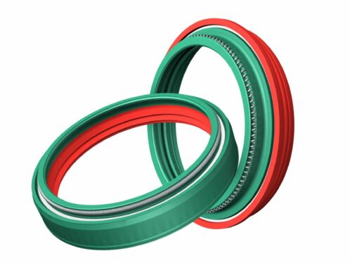
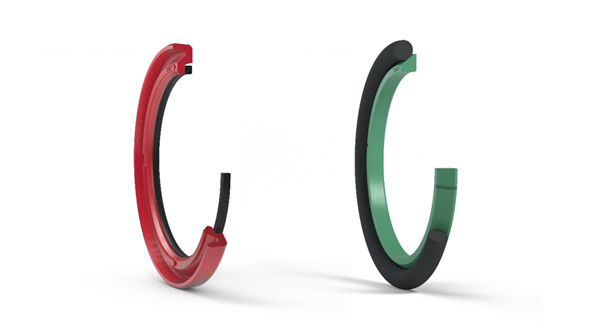
SKF has developed two new friction-optimized buffer seals. The HDB is optimized for use in heavy-duty applications, using a thermoplastic back-up ring to prevent extrusion. The RDB is designed for use in medium-duty applications, using a high-performance hard-grade polyurethane material. The verification tests have been successfully completed for both buffer seal types. Field validation tests of different sizes are still ongoing (and can run for up to one year).
Several factors influence the energy efficiency of a rod seal package in a hydraulic system. To reach the target of a highly efficient rod sealing system, the friction created by the seals must be kept to a mini-mum. But what influences the friction of seals?
To find this out, we need to take a closer look at the contacting area between the seal and the movable counterpart. The influencing factors can be fully explained by the Reynold equation. It says that the flow of a thin lubricant film between two surfaces is influenced by the velocity, the gradient of the contact pressure distribution and the viscosity of the lubricant. The lower the level of lubrication film thickness, the higher the probability of increased friction. Detailed information can also be found in the references /3/ and /4/.
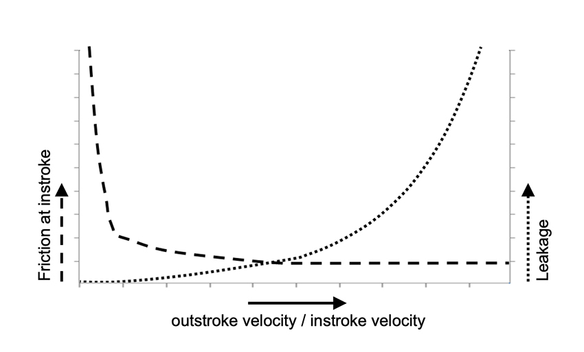
The influence of different instroke and outstroke piston rod velocities has been analysed for a common U-Cup rod seal. Fig. 5 shows that the leakage, more precisely the lubrication film thickness, increases with a higher ratio between outstroke and instroke velocity. Thus, if the outstroke velocity is much higher than the instroke velocity, leakage is more likely, and if the instroke velocity is much higher than the out-stroke velocity, there’s more likelihood of insufficient lubrication, resulting in increased friction when the instroke is high.

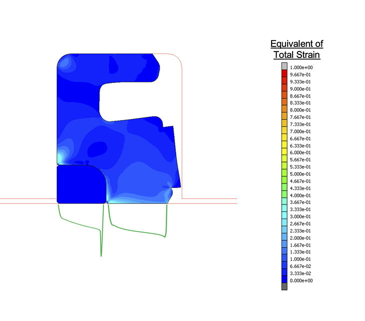
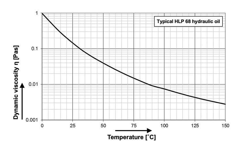
Test rig investigations
1.3 Test rig configuration
Fig. 9 shows a schematic picture of the test rig that was used for the investigations, and a table with used testing parameters. It comprises a pressurized test cell including buffer and primary rod seals as well as static seals and guiding elements. The test rig is also equipped with a moveable piston rod (elec-trical drive), a hydraulic pressurization unit and a friction force detection system based on a ten-sion/pressure force transducer.
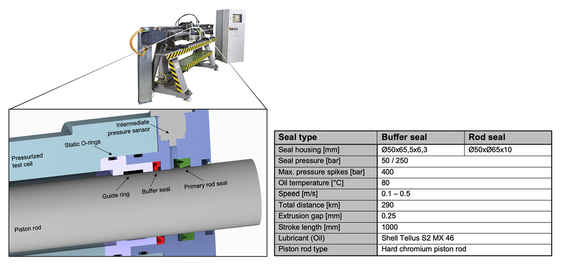
Fig. 10 shows schematically the endurance test used to evaluate the capability to truncate pressure spikes and vent intermediate pressure as the seal ages. The target in defining the test cycle was to veri-fy all buffer seal functions and to be as close as possible to the real application. The test programme includes the following test phases:
- running-in phase to set up constant starting conditions for each package to guarantee a correct comparison;
- pre-performance phase to evaluate characteristics such as absorbing pressure spikes or time to build up intermediate pressure;
- long-term phase to evaluate characteristics such as wear or extrusion resistance; and
- post-performance phase to evaluate characteristics as the seal ages.
Results and discussion
1.5 Buffer seals for heavy-duty applications (e.g., excavators) – the new SKF HDB
The new HDB buffer seal combined with the S1S primary rod seal was evaluated in the endurance test programme and was compared with the benchmark rod seal package, comprising a high-sealability buff-er seal in combination with a rubber U-Cup with an integrated back-up ring as the primary rod seal.
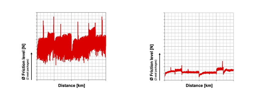
Fig. 11 shows the friction force and visual analysis from the pre- and post-performance test cycle. The difference between a friction-optimized buffer seal (SKF HDB) and a high-sealability buffer seal (bench-mark) could clearly be seen when comparing the friction levels. Furthermore, the benchmark package shows a significant increase in friction during the post-performance test compared with the pre-performance test. This means that the benchmark package was being harmed during the long-term test cycle because of higher operating parameters caused by increased friction. The SKF package shows a quite stable and low-friction force, which is an indicator for a properly working sealing system over the long term.
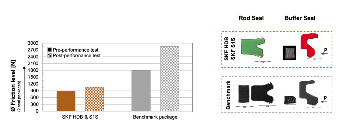
The increased friction of the benchmark package led to an increased temperature of the whole system, which resulted in increased wear of the thermoplastic back-up ring. In addition to this, the visual analysis of the primary rod seal shows increased sealing-lip preload loss caused by higher temperature and in-adequate lubrication.
There was no intermediate pressure between buffer and rod seal at the benchmark package. The SKF package shows a relatively low intermediate pressure, which is a consequence of the design concept of the HDB. In any case, the profile cut of the S1S in Fig. 11 shows that the intermediate pressure hasn’t damaged the primary rod seal. The deformation of the back-up ring of the HDB led to a higher sealability as the seal aged, ending up with there being less likelihood of building up intermediate pressure and lower levels of lubrication. Both packages showed no leakage after the whole endurance test.
The investigations show that the SKF package is more efficient because it requires less energy input due to lower friction. The result is a longer lifetime of the seals and the lubricant and longer intervals between maintenance.
1.6 Buffer seals for medium-duty applications (e.g., forklifts) – the new SKF RDB
Fig. 12 shows the friction level of SKF RDB and a commonly used rubber energized PTFE buffer seal at pre- and post-performance tests, as well as profile cut analysis after the whole endurance test. Both buffers were combined with the same rod seal.
The PTFE buffer is showing a relatively low friction level. The PTFE element is showing extrusion in both directions because it sealed in both directions and did not vent intermediate pressure as desired. As a consequence, the primary rod seal also showed some extrusion, which confirms that the PTFE buffer was not effective in reducing the pressure spikes during the endurance test.
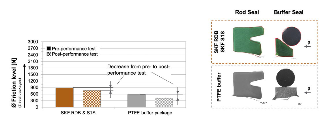
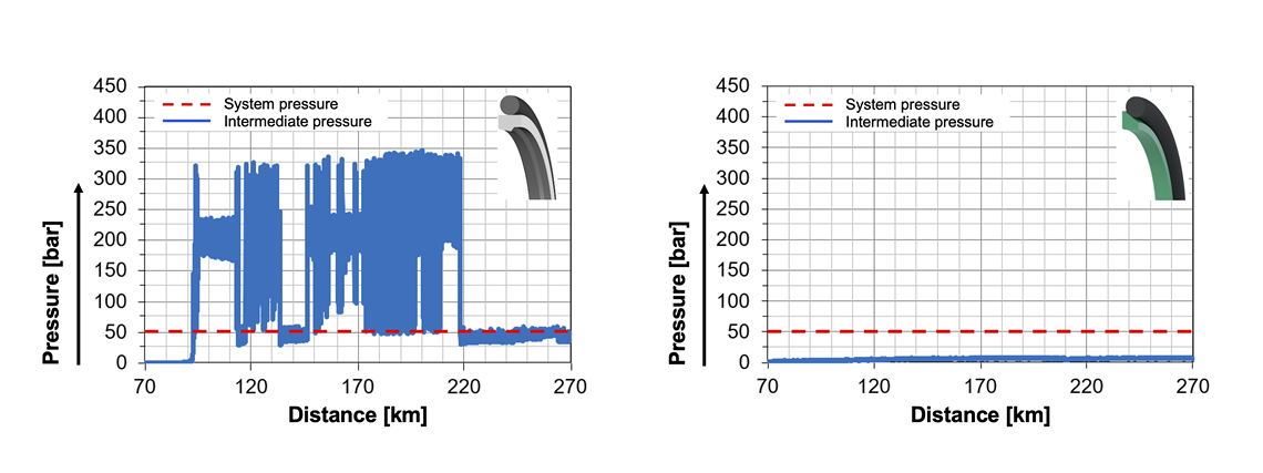
Fig. 13 shows the intermediate pressure at 50 bar backstroke system pressure in the long-term test for both glide ring seals. It could be seen that the PTFE buffer immediately built up intermediate pressure to a multiple system pressure level, which is a result of no venting capability. SKF RDB shows no-to-low intermediate pressure build-up at several pressure stages between 50 and 400 bar.
Summary and Conclusion
This article shows the main functions of rod seals as well as different buffer-seal working principles. The influences of buffer and rod seals on the efficiency of a hydraulic system can be thoroughly explained by the results of the in-house test rig investigations.
The results clearly demonstrate that it is very important to select the right buffer seal type in relation to the operating parameters. Where lip-type buffers with a thermoplastic back-up ring (HDB) can be used up to very high pressures, O-ring energized glide ring seals (RDB) have limitations in extrusion re-sistance; in particular, low-quality PTFE materials can lead to unacceptable extrusion. Consequently, such seal types should only be used in medium-duty applications.
But it’s not only the right selection of the buffer seal type that is important. The primary rod seal and the wiper must be adjusted, depending on the selected type of buffer seal. Please refer to further SKF bro-chures and articles for more information on rod seal package selection.
1.7 HDB buffer seal features and benefits
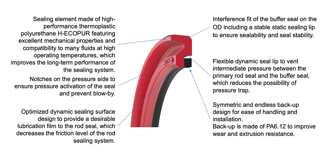
The HDB buffer seal retrofits standard buffer seal grooves (ISO and JIS) and guarantees the lowest possible friction to ensure long seal life. Fig. 14 shows the benefits and features of the product.
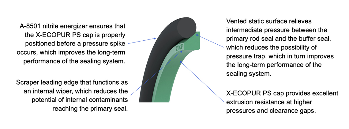
The RDB buffer seal retrofits standard buffer seal grooves (ISO and JIS) and provides outstanding per-formance at a lower cost than other commonly used medium-duty buffer seals. Fig. 15 shows the bene-fits and features of the product.
2 References
/1/ SKF Industrial Seals, Hydraulic seals catalogue, 2014-06-18, page 15
/2/ M.Sc. Pat.-Ing Mario Stoll, Reibkraft S1S Prüfprogramm, Institut für Ma-schinenelemente, Universität Stuttgart, März 2017
/3/ Müller, H.K., Nau, B.S.: Fachwissen-Dichtungstechnik, http://www.fachwissen-dichtungstechnik.de
/4/ Dipl.-Ing. Ulrich Nißler, Prof. Dr.-Ing. habil. Werner Haas, Simulation und Versuch bei Hydraulikdichtungen, 14th ISC Tagungsband, S. 497-511


