Integrated sensor ball bearings
Integrating sensors into bearings reduces the overall number of parts. This, in turn, simplifies assembly and hence reduces weight, space requirements and ultimately, cost.In addition, integration ensures greater system reliability. Indeed, by measuring in close proximity to a precision component, the bearing, it is possible to eliminate air gap variations, caused by possible deflections between the sensor and the impulse ring which can occur in conventional assemblies.
Summary
Bearings with integrated sensors are now reality following the development and marketing of “intelligent” hub bearings for the automotive industry in compliance with the ABS system requirements.
Today, the concept of sensor integration has been extended to include other types of bearings such as deep groove ball bearings.
The technique helps satisfy the growing need for data acquisition, especially in the field of general mechanics, linked to developments in, for example, automation and continuous electronic monitoring of parts or processes for preventive maintenance.
Integrating sensors into bearings reduces the overall number of parts. This, in turn, simplifies assembly and hence reduces weight, space requirements and ultimately, cost.In addition, integration ensures greater system reliability. Indeed, by measuring in close proximity to a precision component, the bearing, it is possible to eliminate air gap variations, caused by possible deflections between the sensor and the impulse ring which can occur in conventional assemblies.
Deep groove ball bearings with integrated sensor (figure 1) are generally used to measure the relative angular displacement of the two bearing rings in order to determine factors such as the speed and the direction of rotation, acceleration, number of revolutions, motion and displacement. This information provides the user with a multitude of control possibilities in such diverse applications as electric motors, gearboxes and linear actuators, while making other detection devices superfluous.
2. DESCRIPTION
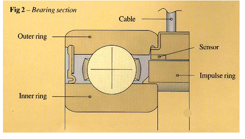
As shown in figure 2, a deep groove ball bearing with integrated sensor comprises :
- a bearing of standard dimensions
- a magnetic impulse ring
- one or two sensors depending on the information required
- a connecting cable
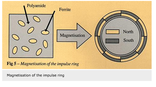
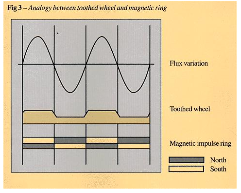
The bearing operates according to the following basic principle: the magnetic impulse ring contains a succession of north and south poles, acting in a manner similar to that of a toothed ring placed in a magnetic field.
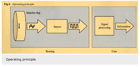
The sensor is attached to the inner ring of the bearing. When the latter rotates, the impulse ring rotates past the sensor designed to respond to the magnetic field variation generated by each change in polarity. The sensor then supplies a signal whose frequency is a function of the number of polarity changes per second. It is thus possible to measure the rotational movement of one ring relative to the other.
Via the connecting cable, the signal is transmitted to an electronic device for processing to allow the required information to be measured and used. This equipment is generally developed by the user (figure 4).
- A standard deep groove ball bearing of ISO dimensions is used. The bearing does not need modification to allow for fixing the sensor components. An existing bearing can be replaced without having to modify shaft or housing bore diameters. Only the extra width of the bearing at one side must be accommodated and a passage should be provided for the connecting cable.
- The impulse ring is a moulded plastic ring on a metal support by which it is attached to the inner ring. The plastic material is polyamide and contains metal particles (ferrite) so allowing the north and south poles to be alternated once the finished part has been magnetised.
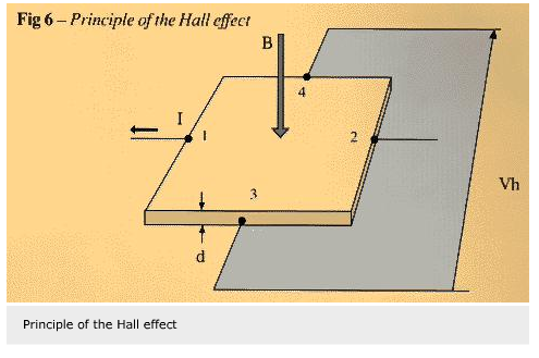
- A Hall effect sensor is used which consists of a discrete semiconductor fed by an electrical current and an integrated circuit delivering a signal that is compatible with the electronic signal processing equipment.
Generally, a gallium arsenide semiconductor is used.
When an electric current, I, flows between its terminals 1 and 2 and is subjected to a magnetic field of intensity B perpendicular to its surface, it generates a voltage, Vh, between its terminals 3 and 4 (figure 6).
The measurement of this voltage determines the magnetic flux variations caused by the rotation of the impulse ring.
The value of supply current I (20 mA) is adjusted by the load resistor, set by the user as a function of the supply voltage.
The value of voltage, Vh, is given by the formula :
Vh = I B Rh/d
where
Rh = Hall constant of the semiconductor
d = thickness of the semiconductor
I = intensity of the supply current
B = intensity of the perpendicular magnetic field
Since Vh is of the order of 100 microvolts, the signal has to be amplified to enable it to be used. An integrated circuit is therefore associated with the discrete semiconductor. This integrated circuit consists of an amplifier and a Schmitt trigger which transforms the sinusoidal signal supplied by the semiconductor into a square signal as illustrated in figure 7.
The sensor in the present case has the dimensions 4.5 x4.5×1.5 mm. It is provided with three small lugs to fix the cable.
Component miniaturisation and the possibility of measuring speeds down to 0 have led to this type of sensor being preferred to alternatives such as inductive or magnetoresistance sensors.
The cable links the bearing with the electronic signal processing equipment. It has a standard length of 50 cm and contains three or four wires, depending on whether one or two sensors are integrated in the bearing. The temperature and environmental resistance meet the requirements of the automotive industry.
As shown in figure 2, the Hall effect sensor and its soldered connection with the cable are moulded in a plastic circular piece mounted in a metal support which forms one piece with the outer ring of the bearing. This type of connection ensures efficient mounting of the sensor on the bearing. In addition, the metal support concentrates the magnetic flux produced by the impulse ring and thus allows flux variations to be detected more efficiently by the sensor.
3. CHARACTERISTICS
The frequency, f, of the signal supplied by the sensor is given by the following formula:
f = N Z/60 (Hz)
where
N = bearing speed (r/min)
Z = number of impulses per revolution
with
f min = 0
f max = frequency corresponding to the maximum bearing speed
(the frequency limitation due to sensor itself is 106Hz)
The measuring accuracy is a function of the number of poles of the impulse ring. Today this number is physically limited by a minimum distance of one millimetre between two poles.
Unless otherwise specified, deep groove ball bearings with integrated sensor are equipped with a ring containing 32 north and south pole pairs, producing 32 impulses per revolution.
The measuring accuracy can be increased by using a bearing with two integrated sensors. It is then possible to double the number of impulses per revolution by processing the signal supplied by each of the sensors. The integrated sensor bearing can be used in a temperature range of -40 to +120 °C. Higher temperatures, up to 150 °C, can be withstood if suitable components are used.
Moreover, the bearings can be greased-for-life and sealed, a standard shield or seal being used at the side opposite to the sensor. The sensor side is protected by a labyrinth.
4. APPLICATIONS
Suitable signal processing of the sensor data during rotation of the bearing allows the following states or factors to be measured:
- stop or motion
- speed
- angular acceleration
- number of revolutions
- distance travelled
By integrating a second sensor it is also possible to determine the direction of rotation.This second sensor is angularly displaced with respect to the first one so that the signals supplied by both sensors are phase-shifted in relation to one another as shown in figure 8.
This phase shift is + or – 90 degrees according to the bearing’s direction of rotation. Processing of the signal thus allows this rotational direction to be determined.
Consequently, deep groove ball bearings with integrated sensor are suited for a wide variety of applications including:
- control systems for automating equipment operation;
- preventive maintenance, where they allow for the continuous supervision of critical installations.
The main application areas where deep groove ball bearings with integrated sensor can be used include the following:
- electric motors: factors generally measured are speed, acceleration, the number of revolutions or the direction of rotation;
- gearboxes, geared motors or differential gears: quantities generally measured are the speed and the direction of movement for synchronisation;
- linear actuators for which angular displacements are measured for position control;
- shafts or spindles for which the angular speed, the direction of rotation or the number of revolutions need to be measured.
5. CONCLUSIONS
The development of sensor-equipped bearings fits in with the objective to integrate other functions into the bearing, so simplifying assembly routines and making for more compact designs.
This integration creates a single element combining both bearing and data acquisition functions. It has been made possible by the miniaturisation of electronic components and the improvement of their capacity to withstand high temperatures.
Emmanuel de Blic,
SKF France,
8 avenue Réamur,
F-92142 Clamart


