Microstructural alteration of bearing steels in rolling contact fatigue
Material degradation is the main reason that rolling bearings fail. The best way to predict bearing failure is to develop a keen understanding of material degradation, in order to predict bearing performance by selecting the optimal steel and heat treatments for specific applications. This understanding also leads to more accurate predictions of remaining bearing life.
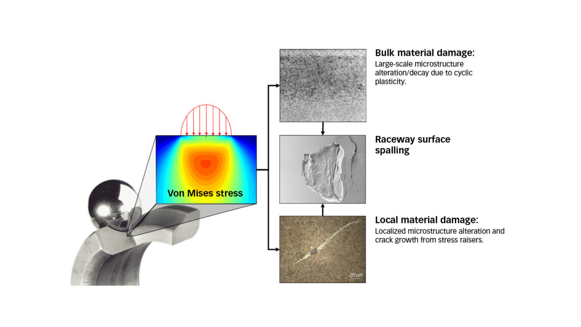
Rolling contact on the raceways of a bearing generates cyclic stresses that extend from the surface to the subsurface regions. If the stress exceeds the local strength limit of the material, damage or degradation of the microstructure will develop, which may eventually lead to raceway surface spalling as a result of rolling contact fatigue (RCF).
Under poor lubrication conditions (viscosity ratio, κ < 1), metal-to-metal contact at the asperities can generate high surface stress. Surface traction, induced by even small amounts of sliding in the contacts, can also generate high surface stress. High surface stress may cause surface fatigue damage, which often manifests as micro spalls or pits.
In rotating bearings operating in good lubrication conditions (κ > 2 ), the maximum shear stress exists at a certain depth beneath the raceway surface. The cyclic shear stress resulting from rolling contact may eventually cause fatigue damage leading to subsurface initiated spalling of the raceway (fig. 1). Under RCF conditions, two types of material degradation may occur. If the maximum contact stress exceeds a certain limit, known as the elastic shakedown limit, the material in a subsurface region undergoes a progressive plastic flow that results in progressive microstructure alteration, which leads eventually to raceway spalling. At a contact stress below the elastic shakedown limit, however, localized damage (depending on the local stress conditions) could still develop from material imperfections such as non-metallic inclusions, owing to the stress-raising effect. This type of damage is characterized by the so-called butterfly, with single or multiple cracks initiated from an inclusion or a pore. The growth of the cracks is accompanied by the development of white etching areas (WEAs). Under certain conditions, growth of a subsurface crack may also lead to spalling of the raceway surface.
The localized fatigue damage resulting from material imperfections in bearing steels has been discussed in a previous article [1]; these types of fatigue damages are particularly relevant for medium and large sizes of roller bearings. Based on a review paper published recently by the authors [2], the current article aims to summarize the studies published in the literature on the microstructural alteration of bearing steels, i.e., the bulk material degradation under RCF. The latter type of material degradation is particularly relevant for small- and medium-sized bearings operating under relatively high contact pressures.
Microstructure of bearing steels
Carbon and chromium are basic alloying elements of bearing steels used to achieve the required hardness through heat treatment. Additional alloying elements are needed to increase the hardenability of steels for large-sized bearing components.
Through-hardened bearing components are normally heat-treated to produce either a martensitic or bainitic structure. The present article focuses on the martensitic structure of bearing steels.
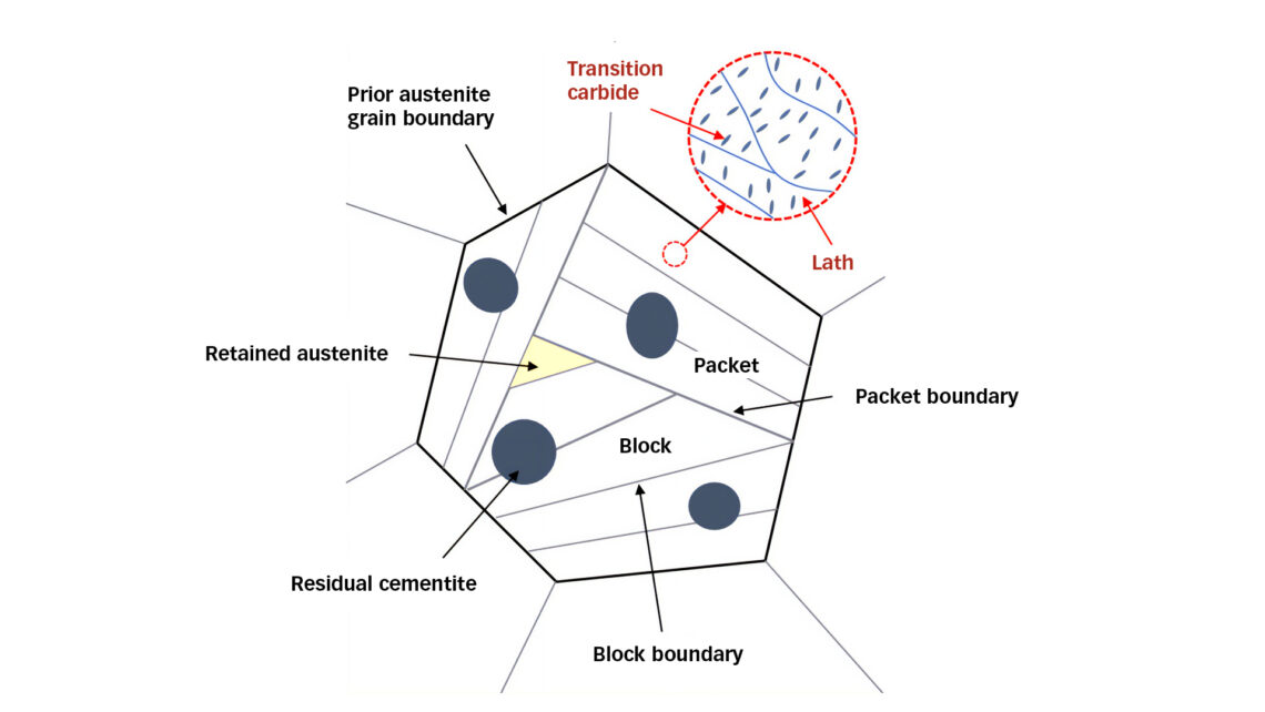
Martensitic hardening involves austenitization, followed by quenching in oil or salt baths, and then low-temperature tempering in order to balance conflicting properties. During austenitization, a fraction of the spheroidal cementite dissolves, leading to a carbon content of 0.6–0.65 wt % in the austenite. Upon quenching, martensite forms with a fraction of austenite retained. The subsequent tempering gives rise to precipitation of transition carbides and further transformation of the retained austenite (RA) to martensite, leading to reduction of the RA content. The RA content decreases with tempering temperature and can diminish to zero if the tempering temperature reaches 220 °C. Fig. 2 shows a schematic representation of the martensitic structure after heat treatment. Inside a prior austenite grain there are martensite packets, residual cementite and RA. Each packet contains blocks in which martensite laths are formed. Transition carbides precipitate inside the martensite sub-grains during tempering.
Material response to RCF
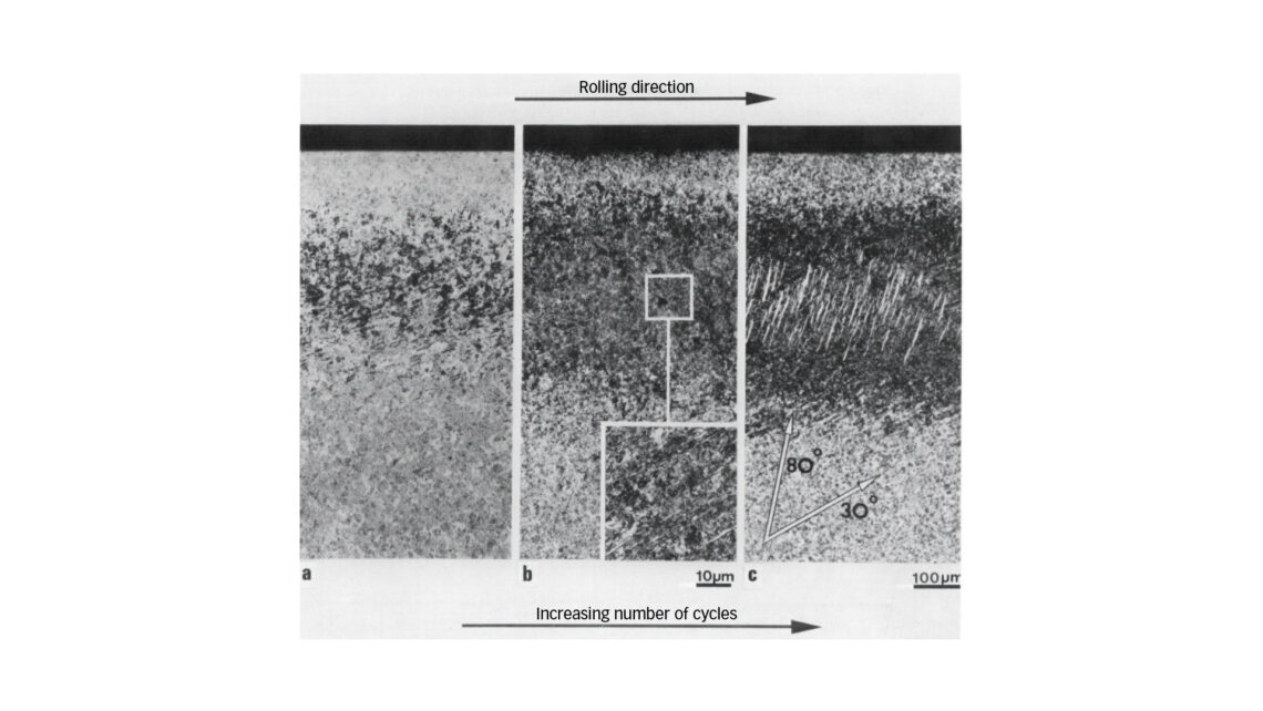
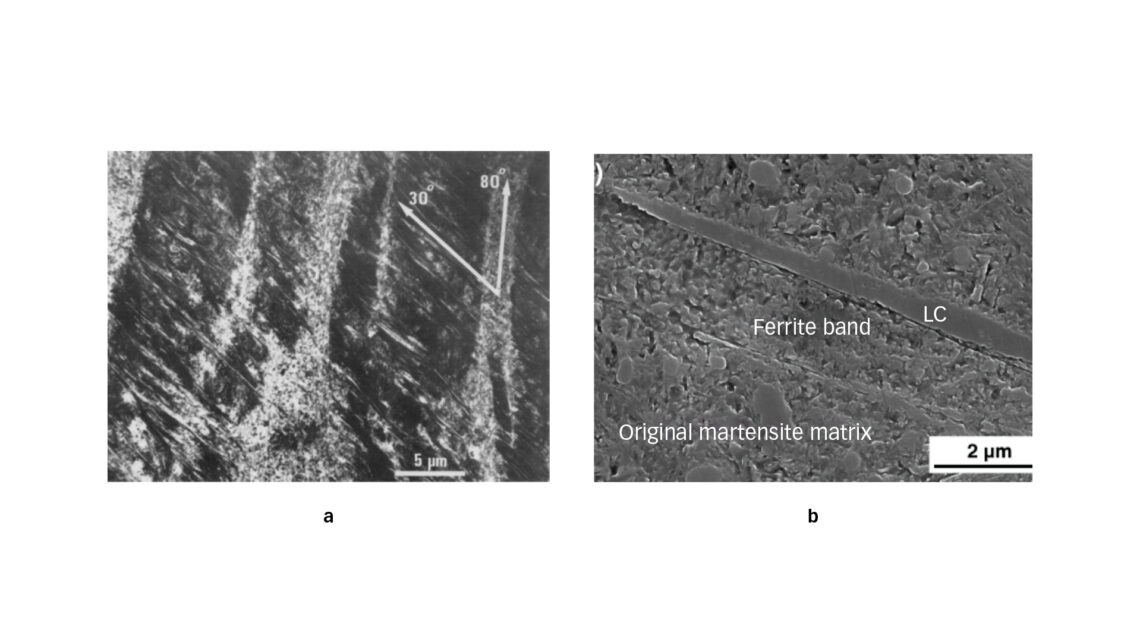
If the maximum contact pressure exceeds the elastic shakedown limit, the bearing steel in the subsurface region undergoes a progressive microstructural alteration as a result of accumulation of microplasticity. Such a degradation process manifests itself under light optical microscopy (LOM) as the appearance of a dark etching region (DER). With the progress of RCF, white etching bands (WEBs) with two distinct orientations develop inside the DER. The formation of the low-angle bands (LABs) with an orientation of about 30 º relative to the over-rolling direction is followed by the development of the high-angle bands (HABs), which are oriented at an angle of about 80 º to the over-rolling direction. Fig. 3 shows a micrograph of subsurface microstructural alteration.
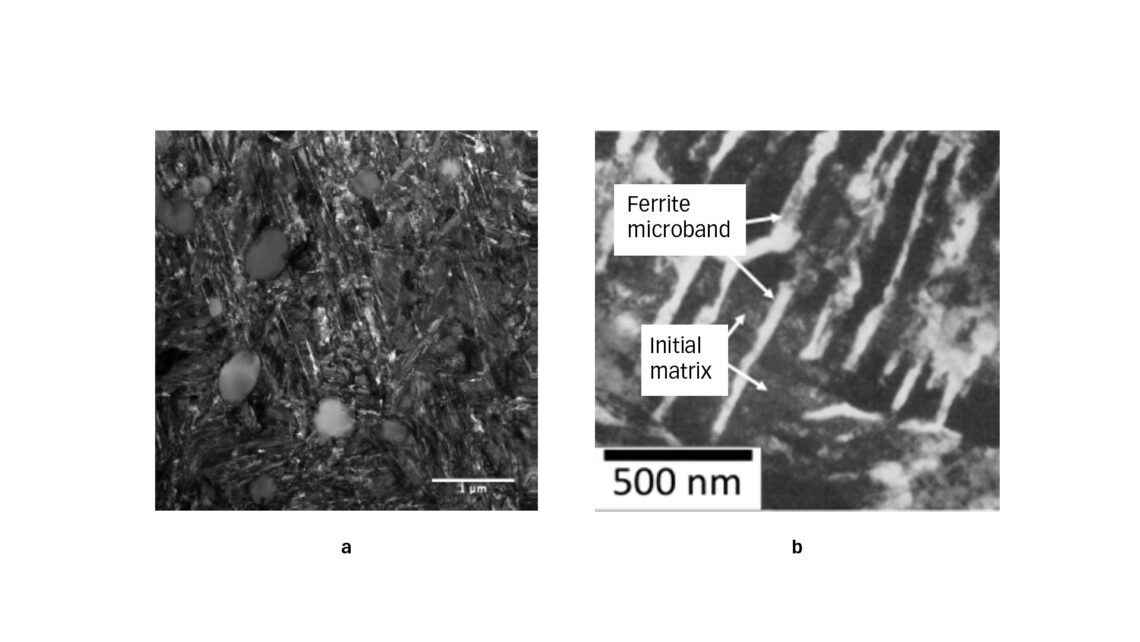
Characterization of the DER using a transmission electronic microscopy (TEM) indicates that ferrite microbands [3, 4] are formed within the martensitic matrix (fig. 4). When viewed from the circumferential section, the microbands are densely spaced or clustered. The microbands in each cluster have the same orientation but can have a different orientation from those in other clusters. On the transverse section (cross section of a ring), however, the microbands appear parallel to the raceway surface. These observations suggest that the microbands are thin plates whose orientation changes only with respect to the over-rolling direction. Furthermore, the microbands can extend across martensite plate boundaries [5].
Another prominent feature visible in the DERs is the elongated ferrite. Elongated ferrite is also formed in the martensitic matrix structure during RCF but appears as individual features and is not grouped like the ferrite microbands. There is an indication that the elongated ferrite grows to form large ferrite grains present at the LABs and HABs [5]. Like the ferrite microbands, the elongated ferrite is of thin-plate shape and lies at about 30 ° or 80 ° to the raceway surface when observed on the circumferential section (fig. 5a). When viewed at the cross section, the bands are parallel to the raceway surface. The LABs and HABs appear white when observed in the optical microscope (see fig. 3). This is why they are commonly called white etching bands (WEBs). Their internal structure can be very heterogeneous across the thickness. Both LABs and HABs can be made up of polycrystalline nano-sized ferrite and elongated ferrite [6].
The appearance of WEBs after about 109 stress cycles is typically observed in conjunction with the formation of lenticular carbides (LC) [7]. Lenticular carbides are formed on the side and parallel to the large WEBs. A fully developed WEB can be 50–60 µm in length and 10 µm in width, while the thickness of a lenticular carbide can reach 1 µm. The formation of lenticular carbides is related to the partial dissolution of residual cementite but does not require the full dissolution of residual cementite [4–8]. Fig. 5b shows a sandwich structure in the WEBs region where a ferrite band and a lenticular carbide lie beside the original martensite matrix [9].
The residual cementite is much harder than the tempered martensite matrix and is thus believed to have a higher resistance to plastic deformation. However, both elongated ferrite and ferrite microbands are observed to grow through the residual cementite, causing it to dissolve [3, 10]. After a large number of stress cycles, the residual cementite particles in the highly stressed region are often found to have blurry edges, suggesting that the cementite is dissolving during the RCF process.
There are several factors that influence or govern the microstructural alteration in RCF, including the initial structure, the residual stresses and the operating conditions, such as contact pressure and temperature. As a thermal-mechanical process, the rate of microstructural alteration increases with contact pressure and/or temperature.
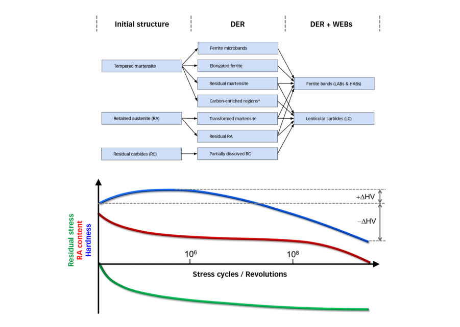
The microstructural alteration is a process of carbon migration driven by plasticity-induced dislocation glide, which is summarized in fig. 6. For bearing steels with martensitic hardening, the initial structure consists of tempered martensite containing nano-sized precipitates (transition carbides), retained austenite (RA) and residual cementite. Formation of DERs involves the transformation of the tempered martensite to ferrite in the form of ferrite microbands and elongated ferrite, as a result of dislocation-driven carbon migration from the martensite matrix. In the meantime, RA transforms partially to martensite as a result of stress- and strain-induced phase transformations, while the residual cementite is intact at the early stage but is gradually dissolved in some regions of highly localized plasticity. With the progression of RCF, the ferrite microbands and the elongated ferrite grains develop further to ferrite bands that are visualized as low-angle bands (LABs) and high-angle bands (HABs). The carbon atoms from the matrix and dissolved carbides are segregated to form lenticular carbides between the ferrite bands.
There exists a dispute as to where the carbon atoms migrate to at the stage of DER formation. The specific question is whether the carbon atoms inside martensite are transported towards the transition carbides [9], causing the so-called carbide coarsening, or to somewhere else, such as the boundaries of the newly formed ferrite microbands or elongated ferrite grains [11].
The fatigue damage of low-temperature tempered martensite under rolling contact is accompanied by the decomposition of RA and the build-up of compressive residual stress, which can be systematically studied by means of X-ray diffraction [12–14]. Although the stress-assisted transformation from RA to martensite occurs from the beginning and continues with the RCF process, such a process is found to correlate with the DER formation and the subsequent development of the WEBs [12, 13]. After a sufficiently large number of stress cycles, a complete decomposition of RA can take place in the highly stressed region.
The microstructural decay is also reflected by a change of hardness. It has been found that the average hardness of the altered structure is noticeably lower than that of the initial structure [9, 13, 15]. It was also observed that an initial slight increase in hardness is followed by a significant hardness decrease in the decayed microstructure after a large number of stress cycles [10, 16]. The initial increase of hardness is a result of work hardening. With the progression of RCF, the dislocation-driven carbon migration leads to increasingly unhomogenized decayed microstructure characterized by carbon-depleted regions mixed with carbon-enriched regions. The carbon depletion in the martensite matrix causes a gradual decrease in hardness of the decayed microstructure.
Concluding remarks
Failure of a rolling bearing is in essence a result of material degradation under given operating conditions. Understanding material degradation is fundamental for the prediction of bearing performance to enable the optimal selection of steels and heat treatments for specific applications as well as prognostication of the remaining bearing life. The prognostication can be useful for validation of the bearing selection or indicate possible changes in the bearing’s operation or maintenance that can prolong the life of subsequent bearings operating in the asset.


