
Thinking beyond rolling bearings: gears
Bearings and gears have a lot in common: both are machine elements that transmit load through lubricated contacts. But they also have important differences: the required number of fatigue cycles is different, as are pressures, speeds and sliding. Here we look at a common way to calculate their lives.
Gears are contacting machine elements that have challenges similar in many aspects to rolling bearings. They also have important differences. In many applications rolling bearings and gears work together in close interaction. Engineers working with rolling bearings are often confronted with the need to have some basic understanding of the working conditions of gears because this can influence the bearings’ behaviour. Yet the life calculation methods are different, despite having similar tribological aspects. In this article, surface life aspects well-known in bearings are applied to gears, and the new surface-subsurface integration method for calculating bearing life is explored for possible extension to gears. In this way, for the first time, rolling bearings and gears can be calculated with exactly the same methodology.
The tribological conditions of the surfaces of gear teeth flanks are similar to the rolling bearing contacting surfaces, but they are different in magnitude. Both kinds of surfaces have rolling/sliding (bearings much less sliding than gears), both have high pressures (bearings higher than gears) and both have surface roughness of the same order of magnitude as the lubricant film thickness. All this points towards the possibility that surface life calculation methods similar to those applied to rolling bearing surfaces can be applied to gear contact surfaces. A good example of this is the SKF surface distress model [1] developed originally for rolling bearings and applied later to gears [2].
However, the rating lives of gears and rolling bearings are calculated in different ways. Selection and design methods for gears are in general based on the Lewis equation [3] for the bending of beams. AGMA standard [4] introduces additional safety factors into the Lewis equation to account for stress concentration in the tooth root, overload and load distribution on the tooth. In addition to the fatigue resistance of the tooth root, AGMA also includes the verification of the maximum stress condition developed at the surface of the tooth contact.
AGMA introduces an equation for the surface durability based on “dry” contact stresses, so that when the contact stress exceeds a certain critical value, it is considered that the gear teeth will spall. These methods have been successfully used to design and size gears over the past several decades. However, with the increasing industrial demand to downsize machine components and reduce energy consumption and manufacturing costs, engineers are constantly looking for more up-to-date ways to optimize the dimensions of mechanical components.
The latest tribology knowledge in automatic lubrication, advanced surface finish and cleanliness control can clearly contribute to gear durability. This can offer new opportunities to reduce over-design and increase mechanical efficiency. Today, within gear standard organizations, considerable effort is made to assess gear microspalling (micropitting) risk [5], which indicates the importance of this topic in terms of the durability of gears. However, until now tribological aspects (so-called microspalling risk) has only been indirectly considered in the gear design process and, contrary to the approach used in rolling bearings, no specific guidelines have been provided with regard to the life expectancy of the gear.
In contrast, rolling bearings through the years have taken advantage of unique and specialized modelling features for the prediction of the expected fatigue life of the rolling contact in relation to the operating conditions. The most significant are:
- the application of Weibull’s weakest link theory of material strength [6], which takes into consideration the material stress volume at risk
- the use of Lundberg-Palmgren dynamic load rating theory [7–8]
- statistical approach in the definition of the fatigue endurance, i.e., 90 % reliability for the L10 life
- the application of Ioannides-Harris [9] fatigue stress criterion, enabling the inclusion of the effect of the lubrication quality and cleanliness in the rolling contact fatigue life.
Moreover, a new general approach for rolling contact fatigue life was recently introduced – the SKF Generalized Bearing Life Model, or GBLM [SKF / Evolution #4-2015 article]. In this new method the surface-originated damage is explicitly formulated into the basic fatigue equations of the rolling contact. It considers the survival probability of the surface as a failure risk that is separated from the Hertzian stresses of the subsurface [10–11]. This opens up new possibilities for the use of specialized tribology models to describe surface-related failures of the rolling contact.
Gears have not yet taken advantage of these modelling concepts. Neither the use of L10 nor of dynamic load rating has really taken off in gear design, despite significant efforts during the 1970s, due to the pioneering work of Coy et al. [12–15].
The objective here is to briefly discuss an adaptation of the model [10] and study its potential application to gears. The main concept is described in fig. 1. The stress areas of the surface and subsurface of the gear contact are analysed separately regarding their contribution to the survival of the gear mesh, but they both are included in the L10 estimation.
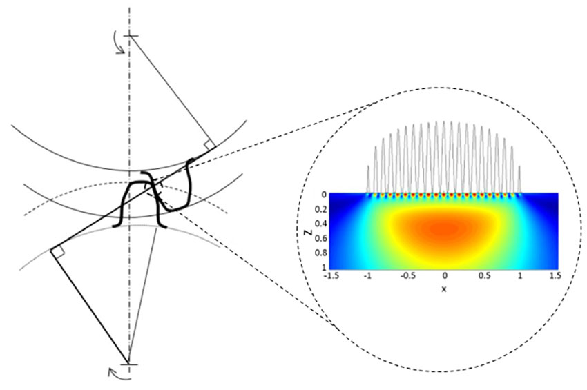
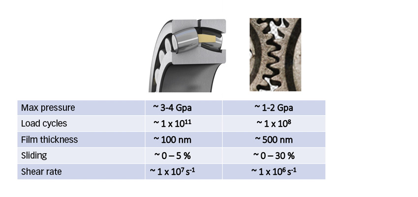
Tribological conditions of rolling bearings and gears
Fig. 2 shows a comparison between gears and bearings of typical tribological conditions. It can be seen that in general the conditions in a rolling bearing seem more demanding than in gears, with higher pressures, longer required lives and thinner lubricant film thicknesses. However, gears show more sliding and have higher roughness, which does not favour the life of the surfaces. Besides this, gears tend to have a surface lay transverse to the rolling/sliding direction, contrary to rolling bearings that in general have a roughness lay along the rolling direction. This, in mixed lubrication conditions, can be an advantage for bearings.
The life of a tribological surface in gears and rolling bearings is mainly determined by two important factors: lubrication quality and solid contamination, both of which are considered in the overall calculation of the rolling bearing life (ISO 281) but not considered fully in the current calculation of gear life. However, the recently developed concept of introducing the survival probability of the surface as a failure risk separated from the Hertzian stresses of the subsurface (the GBLM) might help to consider the same surface aspects in gears as in rolling bearings and unify the calculation methods once and for all.
Surface distress in gears
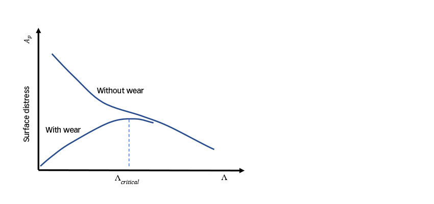
Gears, like bearings, might suffer from surface distress (also called microspalling or grey staining) if the lubrication conditions are not adequate. This can happen in low-oil-viscosity conditions, too-high roughness in gears and potentially low-speed conditions. In other words, at low lubrication quality or low Λ-ratio.
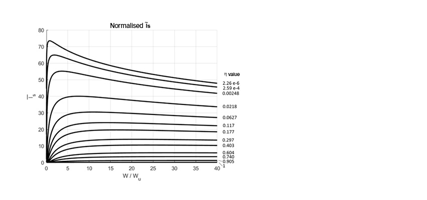
Surface distress is the result of surface fatigue at asperity level in competition with mild wear [1–2]. Sufficient mild wear might remove the asperity peaks and can reduce the local pressures reducing surface stresses and reducing fatigue. Mild wear might also remove the fatigued layers of material. Too little mild wear might prolong the running-in phase of the surfaces, generating more damage and causing more surface distress. For this condition, lower Λ values might result in lower surface distress because wear will increase; otherwise surface distress should increase. This is illustrated in fig. 3.
Another important aspect of surface distress in gears is the case of the so-called negative sliding conditions, when the slower surface is being observed. It is often said that this slower surface is more prone to suffer from surface distress than the faster surface. This phenomenon has been explained in [2], where it is shown that a slower surface will see more micro-cycles of fatigue produced by the roughness of the faster surface, besides the potential effects of surface crack opening and faster propagation.
Gear life with surface and subsurface survival
Full details of the proposed model are given in [16]; however, here it is important to quote the final life equation
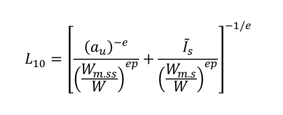
Where:

This life equation (1) has two main terms. The first one (left side) refers only to the subsurface where classic Hertz equations can be applied. The second term (right side) refers only to surface terms, where more sophisticated tribological models [1] are used to estimate the surface damage. This equation follows the same concept as the GBLM developed for rolling bearings.
Equations for the gear dynamic load capacity (subsurface) Wm.ss have been given in the past with the work of Coy et al. [12-15]. An equation for the dynamic load capacity (surface) Wm.s is introduced in [16]. Notice that, unlike with bearings, here a dynamic load capacity for the surface is also introduced. In bearings it would be equivalent to introducing a “C” value also for the surface.
Application case
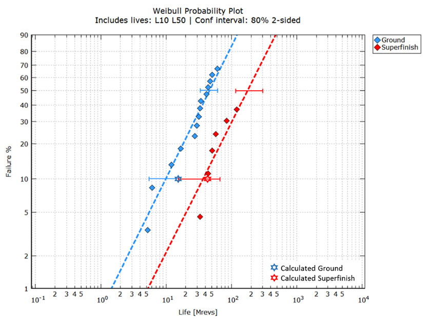
Reference [17] compares the lives of two spur gear populations, one with ground surfaces only and the other with super-finished surfaces. All gear data, materials, geometry and operating conditions are given in the reference. The two populations are tested under the same operating conditions, except that the ground-surface population worsens under lower Λ-ratio due to its higher roughness (Λ≈1.13), and the super-finished surface population shows better lubrication quality due to its lower roughness (Λ≈6.17). The test data presented in [17] for the ground and super-finished gears have been digitized and replotted in fig. 5, depicting a graphical comparison of the measured and calculated data.
Fig. 5 shows that the confidence intervals overlap a little, and more failures would be required (especially for the super-finished variant) to reduce the uncertainty. In any case a clear differentiation in lives can be observed from the data. This figure also shows the calculated lives with the application of equation (1) (stars).
A concept model with surface and subsurface survivals for rolling contact fatigue initially developed for rolling bearings has now been adapted to gears. As an example of application, the effect of lubrication quality has been shown.
The concept model can evolve into a predictive model once calibrated with the use of more experimental results on gears conducted under different application conditions, particularly the effect of material, lubrication, surface finish and particle contamination, which need to be accounted for.
However, even in a concept state the model can give the correct values for tests with spur gears from references [12–15, 17]. For the first time a gear life model shows a rating parameter for the surface (surface dynamic load capacity).
From the analysis presented here, the following conclusions can be drawn:
- The current approach introduces separation of surface and subsurface survival. Therefore, there could be significant gains by increasing flexibility in gear life modelling since more than one region is analysed. This enables engineers to introduce surface failure modes in addition to the Hertzian rolling contact fatigue.
- Since the surface effects are directly incorporated in the formulation, this approach allows for the exploitation of knowledge gained from the use of advanced tribological models. Non-tribological effects could be included in future, such as tooth root stresses.
- The introduction of a surface dynamic load-carrying capacity in addition to the subsurface dynamic load-carrying capacity in gears is an innovation that would give flexibility in rating gears with special features that clearly influence the performance of the surface, such as surface treatments, coatings and surface finishing.
- Particularly in the design of gearboxes, a homologation of life calculation methods between gears and rolling bearings would be extremely useful, not only in the consideration of equal assumptions for bearings and gears but also in the consideration of common reliabilities.


