Turbocharging – more power to your engine
Drive systems are in focus when the automotive industry supports the need to improve diesel engine performance to meet ever-stringent legislation in the European Union and the United States. SKF is actively involved in the development of special rolling bearings for complex turbocharger designs.
Drive systems are in focus when the automotive industry supports the need to improve diesel engine performance to meet ever-stringent legislation in the European Union and the United States. SKF is actively involved in the development of special rolling bearings for complex turbocharger designs.
One potential candidatefor use in diesel engines is the turbocompound drive system. It has particular promise in truck applications. SKF has developed a bearing unit solution for this market based on a flanged and sealed double row angular contact ball bearing. This results in a bearing system that meets the needs of increasingly complex turbocharging designs, including improved performance and lower emissions.
Turbochargers have become particularly important in diesel engines because they offer a considerable increase in engine power with only a slight increase in weight. They play a key role in facilitating the trend towards smaller displacement engines and weight reduction. This technology offers the car/truck owner considerable advantages in terms of fuel economy, drivability and a cleaner environment.
In essence, a turbocharger is an exhaust gas-driven compressor used to increase the power output of an internal-combustion engine. It increases the amount of available oxygen by compressing air that is entering the engine. Hot exhaust gases leaving the engine after combustion are routed directly to the turbine wheel side of the turbocharger and make it rotate. A shaft connects the turbine wheel to a compressor wheel. The rotation of the compressor wheel sucks in ambient air and compresses it before pumping it into the engine’s combustion chambers (fig. 1). Turbo-chargers commonly suffer from what is referred to as “turbo lag.” Because of the basic inertia of the turbocharger rotating assembly, the turbo must “spool-up” to speed before it is able to compress air effectively. Therefore there is no power increase at low engine speeds as the turbo impeller starts to rotate.
To overcome this, diesel engines use turbochargers that are small enough to spool-up by fairly low speeds (approx. 1,700 r/min for passenger engines, and approx. 1,400 r/min for truck-engines). However, one negative effect is that maximum engine power cannot be reached with such small turbochargers. A combin-ation of spooling at relatively low speeds and reaching the maximum engine power can be achieved by using either a multi-stage turbo or variable nozzle turbine geometry (VNT). These two main designs represent the art in turbocharger design.
Multi-stage or registercharging uses two compressors in either serial or parallel configuration. A two-stage system uses two turbochargers in series to achieve high overall system pressure ratios without the need to operate either compressor at high speed. By using a small, low-inertia turbo for one stage and a larger turbo for the other stage, two-stage turbocharging systems are capable of providing higher levels of boost at low engine speeds than a conventional single stage turbo, whilst at the same time providing high pressure ratio capabilities over a wide operating range.
VNT is an approach used for commercial diesel engines. A VNT uses an adjustable inlet guide vane ring, or nozzles, to direct flow into the turbocharger turbine (fig. 2). When the vanes are closed, flow is directed tangentially into the turbine wheel. This imparts maximum energy into the turbine, causing the turbocharger to spin faster. Conversely, when the vanes are opened, they direct flow into the turbine in a more radial direction. This reduces the angular momentum of the flow going into the wheel, producing less turbine work and ultimately slowing down the turbocharger.
Therefore, at high engine speeds, the vanes can be opened to control boost pressure without waste gating. This provides excellent fuel economy at high engine speeds. The adjustability of the VNT allows the turbocharger to optimize itself on the fly to enable the engine to produce maximum torque with maximum fuel economy.
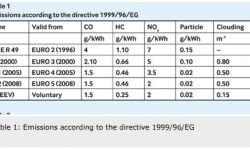
The growth in interest in the turbocompound drive comes from the need to reduce harmful emissions further. According to Directive 1999/96/EG of the European Commission (table 1), emissions of gaseous harmful substances and the pollutant particles from internal combustion must be within certain limits.
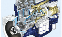
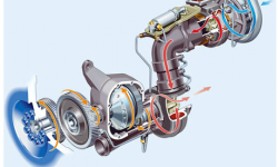
In the contextof automotive or truck diesel engines, turbocompound means the introduction of a power turbine downstream or after the turbocharger. This power turbine recovers a percentage of the thermal energy that would normally be lost through the engine’s exhaust. The mechanical energy generated by the power turbine is fed back into the engine crankshaft via a sophisticated mechanical transmission. The exhaust turbine differs from a standard turbocharger in that it does not have a compressor stage (fig. 3). A mechanically coupled system that is driven directly from a standard turbocharger might also be possible. Energy recovery using a secondary exhaust turbine and transmission can increase efficiency from 42 % to as much as 46 %.
In simple terms more energy is extracted from the fuel consumed. This creates a more powerful engine and provides better efficiency.
As part ofthe turbocompound concept, the turbine (fig. 4) is a key design element, running with maximum speeds of up to 70,000 r/min. The gear ratio from the exhaust turbine to the turbocompound intermediate shaft is 6:1, and the gear ratio from the intermediate shaft to the crankshaft is 5:1. Torsional vibration caused from the internal combustion engine process would be increased by the overall gear ratio of 30:1, which could destroy the turbine. To reduce torsional vibrations the turbocompound intermediate shaft is equipped with a hydrodynamic coupling (according to the Föttinger principle). The slip inside the coupling is normally 2 %. This slippage represents the losses of the coupling and increase in the oil temperature of the engine (fig. 4).
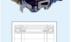
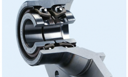
For this application SKF has developed a flanged and sealed double row angular contact ball bearing unit (fig 5). This is clamped onto the rotor shaft with a locknut. The outer ring profile is designed to carry and support the drive gear of the turbocoupling on the outer side and to fix the pump wheel of the turbocoupling on the opposite side. The turbine wheel of the turbocoup-ling is fixed to the turbocompound rotor shaft.
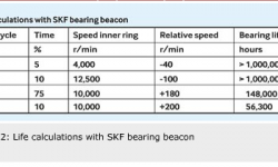
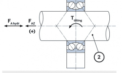
The bearing is required to operate at a temperature ranging from – 40 °C up to 125 °C. The driving clutch side turns nominally faster, i.e. , the outer ring of bearing always turns faster (+) or slower (-) than the inner ring. The bearing unit is loaded radially, axially and also with tilting loads because the drive gear is helical (fig 6). The hydraulic loads act only axially. A represen-tative load cycle for the operating time has been considered. Idle running is expected for 5 % of the time, brake load for 10 % of the time, then two nominal load cases for the remaining time (table 2).
The fatigue life was found to be greater than 56,000 operating hours for all load cases. This exceeds current diesel engine requirements, which typically have a design life of around 15,000 hours.
To analyze the effectof tilting forces and optimize the bearing design, a sophisticated modelling tool is required. For this purpose, engineers used the SKF bearing beacon computer program. The calculation provides results for the bearing fatigue life (table 2). However, to ensure good performance of this bearing other factors are also important. The bearing must have better than normal running accuracy (P5 for all components), a long grease life (> 15,000 h) and, in particular, any out-of-balance forces must be kept to a minimum. In addition to theoretical results, bearings were also examined after field endurance tests. Almost no wear was apparent on the bearing raceways or the rolling elements. Overall, this bearing system can improve the peak efficiency of the Carnot cycle from 42 % to 46 %.
The optimization work carried out on this bearing arrangement includes:
-
Outer ring: the outer ring was optimized regarding both heat treatment (induction hardening) and geometry (using FEM simulation).
-
Inner rings: special care was taken regarding preloading and fits.
-
Shaft-sealing ring (Garter seal): provides grease retention at heavy centrifugal loads, also, the seal lip must exclude contaminants from the engine oil outside.
-
Cage: the improved polymer cage material PEEK (polyetheretherketon) is used. This material is extremely resistant to ageing at high operating temperatures.
-
Grease: the polyurea grease selected must guarantee lubrication for the expected lifetime of the truck engine, which is longer than 15,000 operating hours.
-
Balls: the rolling elements are identified as critical components, so 100 % crack inspection is performed.
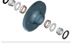
A further developmentof the turbocoup-ling in the turbocompound system is the integration of a gearwheel into the flanged bearing unit (fig. 7). As a result of this enhancement further improvements are possible, including further reduction of the rotating masses, fewer components leading to simpler logistics, further downsizing opportunities, simpler chain of production tolerances and further improvement regarding rotor balancing.
Another interesting application is the turbocharger itself. The main innovation in this concept is to use ball bearings instead of plain bearings (fig. 8). The requirements for lower friction torque and the demand for higher speeds and increased running accuracy were solved with the help of a cartridge unit design. Although sliding bearings have conventionally been used for truck diesel turbochargers, engine designers aiming for better performance have begun to use rolling bearings. Special single row hybrid angular contact ball bearings with a special light alloy cage have been found to offer superior performance, even under high-speed and high-temperature conditions. In the SKF design, a customized bearing unit with tailored distance rings including oil injection was chosen to deal with relatively high speeds, n×dm-value up to 2,000,000 mm/min, in this application.
The calculated bearing fatigue life for all load cases exceed the minimum requirement of 15,000 operating hours, provided adequate lubrication and cleanliness. This means the oil cleanliness (contamination ηc ) has to be 0.3 or greater. Special care must also be taken regarding the oil injection. The oil jet has to pierce the air turbulence (wind-whirl) around each bearing row to lubricate the contact areas of the rolling elements and the cage. This function must be assured during all engine load cases, including the severe condition known as “soak-back,” which occurs in an emergency stop.
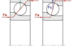
At high speeds,centrifugal forces on the balls will influence the internal bearing forces considerably (fig. 9). This influence is more important in bearings with a large contact angle, since the axial components of the centrifugal forces increase with increased contact angle, and all act in the same direction. For angular contact ball bearings arranged in pairs, this means that the two bearings internally load up one another.
From the results achieved with the SKF design, it seems likely that plain bearings will be replaced by rolling bearings in turbochargers. Diesel motor engine efficiency tests have confirmed the increase of the efficiency of the Carnot cycle raising up to 49 % when using registered turbosystems and ball bearings.
To reach a Carnot efficiency of 50 % is very likely in the next few years. Rolling bearings contribute by their tribological optimized (unit-) design, engineered surfaces and sophisticated materials to the efficiency improvement. It is very likely that more and more diesel truck manufacturers will announce more complex turbocharging systems where the turbocompound together with, e. g., SCR (selective catalytic reaction) Catalysator will play an important role.
The combination of these technologies within rolling bearings can trigger breakthroughs in the design of the diesel engines for the truck industry – and help innovative companies to gain a competitive edge.


