Engineering Competence

Understanding vertical shaft mounting for bearings

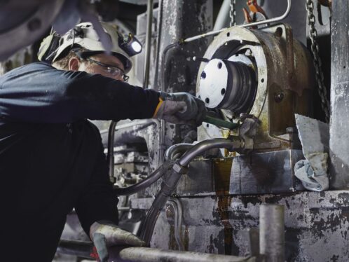
When mounting bearings, one of the most common procedures is to use a vertical shaft mounting position and work with heat. Considering all common mounting methods, as many as one in six bearings may fail because of inadvertent damage sustained during mounting. Commonly used as is, the vertical shaft procedure presents some lesser-known risks. This article discusses potential problems and how to overcome them.

Related Content

Hot mounting of bearings and other components such as couplings and gears has proven to be very practical. The heating, mounting and shrinking of components is well understood, and induction heating is both fast and cost-effective. Handling components in a vertical position is relatively easy: centring of components mounted vertically is straightforward, and gravity helps to keep a component correctly pressed against the abutment when it cools and shrinks.

It is important that mounting after heating is accomplished rapidly to avoid temperature losses that may cause the component to become stuck in the wrong position or cause other damage.

Fig. 1: Vertical shaft mounting.

Options for heating and mounting

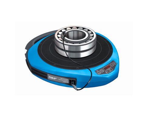
There are a number of different options for the mounting procedure using heat. Common ones include:

  • warm bearing fitted on a room-temperature shaft seat;
  • room-temperature shaft placed in a warm bearing;
  • room-temperature bearing placed in a warm housing; and
  • warm housing fitted on a room-temperature shaft-mounted bearing.

However, bearings behave differently than other components during vertical mounting. All the options will initiate an increase in clearance in the bearing followed by a decrease during the various heating and cooling cycles. Bearings have a relationship between the axial and the radial clearance that is defined by the contact angle. In double-row bearings this is given by the equation:

a = 2.3 x Yo x ∆ r (∆ a is typically 5 – 15 times the radial clearance).

So a small radial movement (i.e., a change of clearance) results in a large axial movement.

Fig. 2: Bearings have a relationship between radial and axial clearance.
On a vertical shaft a bearing will undergo axial motion when there is a change in radial clearance. This can be shown (fig. 3) by first considering a warm bearing (shown in red). Both rings are at the same temperature, and there is a small bearing clearance. The bearing is supported on the outer ring. The inner ring is slightly displaced downwards. When a room-temperature shaft is inserted and lowered to the ring, the inner ring becomes cooled by the shaft as indicated by the grey colour (fig. 4). The inner ring becomes smaller, hence increasing the bearing clearance, and the inner ring is now axially displaced downwards, thanks to the enlarged axial clearance.
Fig. 3: On a vertical shaft, radial clearance change results in axial motion.
Fig. 4: The inner ring is slightly displaced downwards.
Eventually the outer ring reaches room temperature (fig. 5) and matches the temperature of the inner ring, resulting in a small bearing clearance. However, the inner ring has now been forced upwards since the clearance was reduced.
Fig. 5: Sometime later, the outer ring is also at room-temperature.
While this is interesting from an applied-physics perspective, what are its practical implications?

Firstly, we have to consider the movements and forces inside the bearing (fig. 6).

Fig. 6: Movements and forces inside the bearing. First sequence: Inner ring moves downwards.
Initially the inner ring moves downwards and the vertical load (M x g) is carried by the lower row of the bearing. There are roller loads (shown in red) and frictional loads (shown in black).

There is also a contact angle, α and a number of rollers, Z. Using the equation:

N=(M x g)/Z(sin(α)+µ x cos(α)) we see that friction reduces the roller load.

However, in the second sequence, when the inner ring moves upwards, the vertical load (M x g) is now carried by the lower row. Hence the equation becomes N=(M x g)/Z(sin(α)-µ x cos(α)) and the friction is reversed (fig. 7). If sin(α) = µ x cos(α), the upwards motion will create very large roller loads, and the practical consequence is a risk of self-locking or smearing.

Fig. 7: Second sequence: Inner ring moves upwards.
There are combinations of coefficients of friction and contact angles that can result in self-locking (fig. 8). From this figure indications for self-locking are when contact angles are 4 to 15 degrees while the coefficient of friction ranges from 0.05 to 0.4. The potential damage associated with self-locking is plastic deformation that results in noise, vibration and early spalling.
Fig. 8: Combinations of friction and contact angles that self-lock.
Furthermore, outside the self-lock zone there is an additional zone where smearing may occur (fig. 9). In this case friction is sufficient to stop the initial motion but not to resist motion at a higher load. While large contact forces develop, the roller eventually moves axially. In this scenario the damages associated with axial motion at high contact force are burnishing or, in the worst case, smearing.
Fig. 9: Combinations of friction and contact angles that almost self-lock.

Practical outcomes

From this, two potentially harmful outcomes have been identified for both self-locking and “almost self-locking”, which are often seen in machines but rarely considered as directly related to mounting procedures. Fig. 10 shows some of the common damages to bearings.

In the case of a wind turbine main shaft, which is standing on the floor, the bearing is warmed and mounted from above. The bearing inner ring then rests on an abutment, and the bearing cools while the housing is warmed. The warmed housing is then mounted from above and rests on the outer ring.

Measurements are taken during the first hour of temperature equalization (fig. 11).

Fig. 11: Wind turbine main shaft standing on the floor.
In this diagram there are three different zones. In Zone 1 the warm housing is placed on the outer ring. The outer ring with the housing moves downwards due to the load, causing radial deflection that causes axial motion. In Zone 2 the warm housing heats the outer ring, which expands. Clearance increases. Now the outer ring with the housing moves downwards as long as the temperature of the outer ring increases. In Zone 3 the outer ring is no longer warming, and as the housing cools further, the outer ring moves upwards, since the clearance is reduced. The motion sequence includes an example of stick-slip behaviour (marked by red circles). A mounting inspection was carried out, and there was clear evidence of surface burnishing (fig. 12).
In a second case, ring measurements were carried out in an industrial gearbox application where the shaft and gear are mounted vertically. Firstly, the bearing is placed in the housing and a distance ring is positioned on the inner ring. Then a warmed gear is placed on top of the distance ring/inner ring Finally, a cooled shaft is inserted through the gear and into the inner ring. In this case the axial motion is measured. As this is a monobloc design, the casing is turned sideways (fig. 13).
Fig. 13: Monobloc design with the casing turned sideways.
In this instance there were two mounting sequences. In mounting sequence 1, the room-temperature casing rests on a mounting stand and the room-temperature bearing is mounted sideways into the casing and then down. The bearing outer ring rests in the casing and finally a room-temperature distance ring is placed on top of the inner ring. For mounting sequence 2, while the room-temperature casing with the bearing is still resting on the mounting stand, a warm gear is mounted sideways into the casing and then down. The gear now rests on the distance ring and in turn on the inner ring. Then a very cold shaft is mounted from above, through the gear and the distance ring and into the inner ring.

Measurements were taken during the first 90 minutes of temperature equalization. A dummy housing was used to facilitate the measurements (fig. 14).

Fig. 15: Measurements of motion during cooling.
Once again three different zones can be identified. In Zone 1 the inner ring is cooled by the very cold shaft. Clearance then increases. The inner ring with the shaft and gear moves axially downwards. In Zone 2 the warm gear has heated the shaft, and the warm shaft now warms the inner ring. The inner ring then expands. Clearance decreases. The inner ring with the shaft and gear moves upwards. Zone 3 indicates that real motion between rollers and raceway has probably stopped. It is likely that the measurements have included temperature-related dimensional changes of the complete stand. The measurements highlight that there may be two “stick-slip” occasions (marked by red circles).

In this case, the appearance of the lower inner ring raceway in the test bearing was studied after dismounting the test bearing. Thin axially oriented marks were visible.

However, not all roller contacts left such marks. Under the microscope, the thin axially oriented marks showed to partially consist of smeared material.

This damage will copy due to the overrolling and develop into surface distress/wear.

To avoid mounting-initiated damages there are three factors to work on. Firstly, it is important to reduce or eliminate the bearing load during the mounting sequence. The logical path is to avoid vertical mounting and/or to counteract gravity. If this is not possible, mount vertically, but then tilt horizontally to reduce the axial loading during cooling. Try to release friction by rotating to release and avoid motion by centring axially during cooling. Above all, awareness is key, as being aware of the potential damage during mounting helps reduce risk.

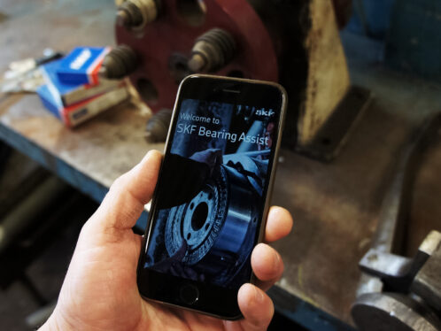
SKF has considerable strengths in bearing mounting, and its BearingAssist app can help with mounting issues. SKF can also support with training fitters on best practice as well as help to review machine design and bearing mounting procedures for all types of equipment.

Related live webinar

Join us on Thursday 30th September, and take the opportunity to hear Hans Wendeberg, Senior Engineering Expert and Linus Wahlterius, Manager New Digital Solutions, talk about the details of vertical bearing mounting and SKF latest tool to ensure correct mounting; SKF Bearing Assist. For more information and links to access the live event click here.

Keep me updated

Want to learn more about what is driving change in the engineering world? EVOLUTION helps you to stay up to date with emerging trends as well as the latest technology. Sign up for EVOLUTION updates to receive new content directly to your inbox.

Sign up